5300Vrms isolation with AC/DC input — what it buys you
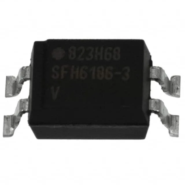
The Vishay SFH6206-3T is a single-channel phototransistor optocoupler in a 4-SMD gull-wing package. Its headline rating is 5300Vrms isolation between input and output, which qualifies it for reinforced insulation in mains-referenced circuits — think offline power-supply feedback loops, motor-drive interface isolation, and industrial PLC input modules where you need to break ground loops. The AC/DC input type means the internal LED handles reverse voltage natively, so you can drive it directly from an AC signal line (e.g., 50/60 Hz zero-crossing detection) without an external series diode. That simplifies the BOM by one part and one solder joint per channel.
CTR bin — the gain decision
The "-3T" suffix denotes the current transfer ratio bin: 100% minimum to 320% maximum at a forward current of 10mA. That is a wide spread — a factor of 3.2 from low to high. For a digital input where you just need to saturate the output transistor, the 100% floor gives you guaranteed logic-low with a 1mA input after the LED drop. But if you are designing an analog isolator or a slow-speed serial link, the CTR spread directly affects your threshold and timing margins. The 400mV Vce saturation at the output side means the transistor pulls within 0.4V of ground when driven into saturation — clean enough for 3.3V and 5V logic families without a pull-up resistor adjustment.
Switching speed and output ratings
Rise and fall times are both 2µs typical; turn-on time is 3µs, turn-off 2.3µs. That puts the usable data rate around 100 kbps — fine for 50/60 Hz mains sync, relay drive, or status feedback, but not for high-speed isolated SPI or CAN. The output transistor is rated for 70V collector-emitter and 50mA continuous current per channel. That 70V ceiling covers 24V industrial logic rails and 48V telecom supplies with margin. The 50mA output can drive a small relay coil directly or sink an LED indicator without a buffer transistor.
Package and temperature — board-level fit
The gull-wing leads are visible for solder-joint inspection — no hidden joints under the body. Not rated for under-hood (125°C+) but fine for most power-supply and motor-drive applications where the optocoupler sits away from the hot components. The 1.25V typical forward voltage at 10mA is standard for an IR LED; the 60mA absolute-maximum forward current gives headroom for pulsed operation if you need higher instantaneous CTR at low duty cycles.