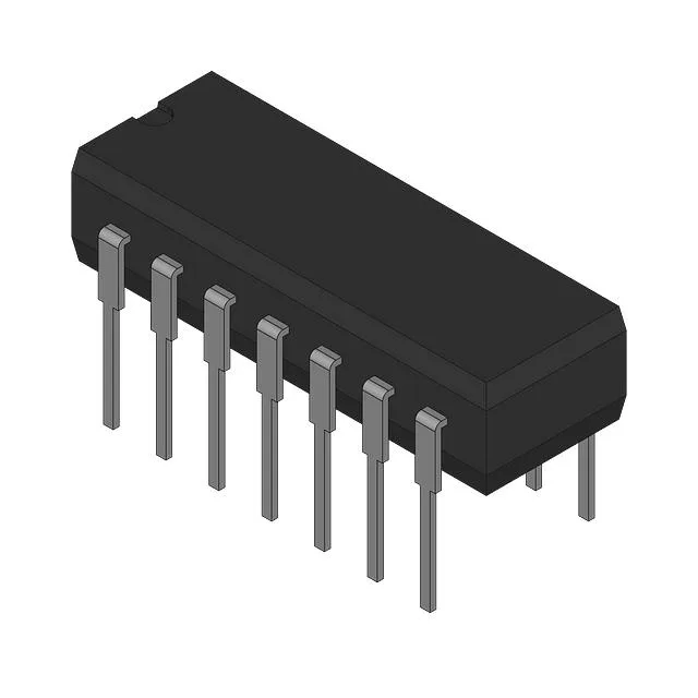
AND-OR-INVERT logic in a ceramic DIP
The Texas Instruments 54F64DM is a single-circuit AND-OR-INVERT gate with 11 inputs arranged as 4, 2, 3, and 2 across the AND-OR structure. Housed in a 14-lead CDIP (0.300-inch body) with a CERDIP die carrier, this through-hole package is rated for the full military temperature range of -55°C to 125°C. The ceramic hermetic seal and lead-frame construction make it suitable for avionics, satellite, and downhole instrumentation where plastic packages would outgas or crack under thermal cycling.
Output drive and input structure
The output is rated for 20 mA source current and 1 mA sink current — a strongly asymmetric drive that reflects the totem-pole topology of the 54F family. The high-side can drive a TTL fan-out of about 10 loads, but the low-side sink is limited; any load that draws more than 1 mA into the output will pull the low-level voltage above V_OL(max). Budget the sink current carefully when driving a bus or LED indicator. The 11 inputs are standard TTL-level without Schmitt trigger hysteresis. With 4.5V minimum supply, the input threshold V_IH is typically 2.0V — noisy or slow-rising signals near the threshold may cause multiple transitions unless externally conditioned. The single-circuit layout means all 11 inputs share one gate; unused inputs should be tied to V_CC or GND through a pull resistor to prevent floating-node oscillation.