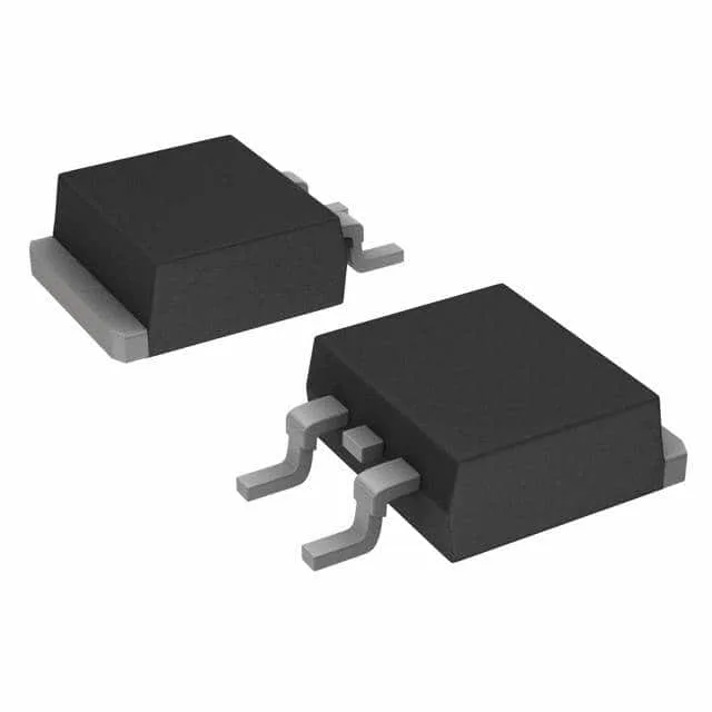
Infineon Technologies AIGB15N65H5ATMA1 — Logic ICs

AIGB15N65H5ATMA1 IGBT, 650 V, 30 A, TO-263, AEC-Q101

MPNAIGB15N65H5ATMA1
End of Life

Infineon AIGB15N65H5ATMA1 NPT IGBT, Automotive AEC-Q101 Trenchstop™ 5 series, 650 V collector-emitter breakdown, 30 A continuous collector current, 2.1 V Vce(on) at 15 V, 15 A, 175 °C junction temperature, PG-TO263-3-2 surface-mount package.

$3.31Ref. price · indicative, final on quote
PackagingTO-263-3, D²Pak (2 Leads + Tab), TO-263AB
StockContact for availability
MOQ1 pcs
  • 100% new & originalTraceable channels only — no refurbs, no pulls, no remarked parts.
  • Date & lot codes on quoteStated per line before you commit; label photos on request.
  • MSL-compliant ESD packingMoisture-sealed bags with indicator cards; reels photo-verified.
  • PayPal buyer protectionPay by T/T, PayPal or Payoneer — card payments covered end to end.

Specifications

AIGB15N65H5ATMA1 Technical Specifications
ParameterValue
SeriesAutomotive, AEC-Q101, Trenchstop™ 5
IGBT typeNPT
Input typeStandard
Mounting typeSurface Mount
Voltage - collector emitter breakdown650 V
Current - collector (Ic)30 A
Current - collector pulsed45 A
Power - max105 W
Operating temperature-40°C ~ 175°C (TJ)
PackageTape & Reel (TR); Cut Tape (CT)
Gate charge40 nC
CaseTO-263-3, D²Pak (2 Leads + Tab), TO-263AB
Test condition400V, 7.5A, 39Ohm, 15V
Switching energy0.16mJ (on), 0.04mJ (off)
Td (on/off) @ 25°C24ns/22ns
Vce(on) (Max) @ vge, ic2.1V @ 15V, 15A

Product details

650 V NPT IGBT for automotive traction and PFC stages

The Infineon AIGB15N65H5ATMA1 is a 650 V, 30 A NPT (non-punch-through) IGBT from the Automotive Trenchstop™ 5 series, housed in a PG-TO263-3-2 (D²Pak) surface-mount package. Key features include a 2.1 V typical saturation voltage at 15 A and 15 V gate drive, a 40 nC gate charge, and a 175 °C maximum junction temperature — the latter critical for surviving the thermal cycling of motor drive and power factor correction (PFC) stages in hybrid/electric vehicle inverters, DC-DC converters, and industrial servo drives.

Ratings that drive the design decision

The 650 V collector-emitter breakdown voltage gives a comfortable derating margin on a nominal 400 V DC bus, absorbing the inductive clamp spikes common in hard-switched inverter bridges without avalanche failure. The 30 A continuous and 45 A pulsed collector current ratings size the part for motor drives in the 1–3 kW range, depending on thermal management. Switching energy is specified as 0.16 mJ (turn-on) and 0.04 mJ (turn-off) under the test condition of 400 V, 7.5 A, 39 Ω gate resistor, and 15 V gate drive. These numbers let you estimate switching losses in a hard-switched topology at a given frequency. The 24 ns / 22 ns typical delay times (on/off) at 25 °C confirm the part is fast enough for 20–50 kHz switching without excessive dead-time overhead. Gate charge is 40 nC. The 2.1 V Vce(on) at 15 A sets the conduction loss baseline.

Package and mounting — TO-263 (D²Pak) surface mount

The PG-TO263-3-2 (D²Pak) is a surface-mount package with an exposed metal tab for heat sinking through the PCB.

Frequently asked questions

Can AIGB15N65H5ATMA1 be used in motor drives?

Yes, the 650 V breakdown voltage and 30 A continuous current rating, combined with the 175 °C junction temperature and AEC-Q101 qualification, make this IGBT suitable for motor drive applications — particularly automotive traction inverters, industrial servo drives, and PFC stages where the DC bus is 400 V or lower. The 0.16 mJ / 0.04 mJ switching energies at 400 V, 7.5 A give a starting point for loss budgeting in a hard-switched inverter.