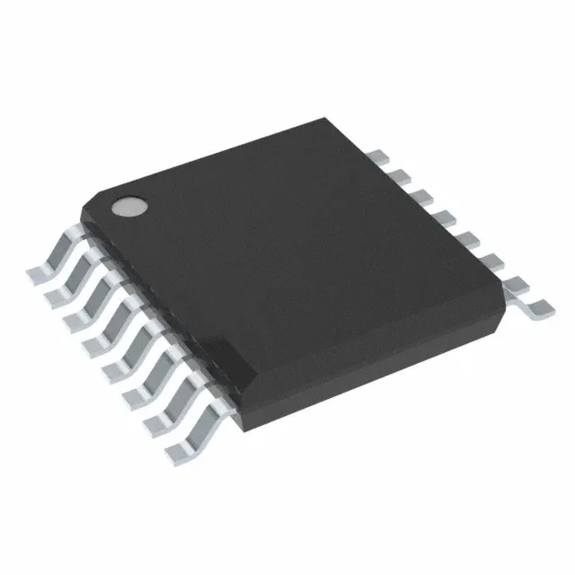
Texas Instruments PCA9554ADBR — Interface & Transceivers

PCA9554ADBR I2C GPIO Expander, 8-bit, 400 kHz, 16-SSOP

MPNPCA9554ADBR
Active

Texas Instruments PCA9554ADBR, 8-bit I2C/SMBus GPIO expander, 400 kHz clock, 2.3 V to 5.5 V supply, push-pull outputs, 10 mA source / 25 mA sink per pin, interrupt output, POR, -40°C to 85°C, 16-SSOP package, Tape & Reel.

$0.7590Ref. price · indicative, final on quote
Independent supplier — new & surplus stockAuthenticity-screened · ESD-safe packingListing updated Aug 2026

Specifications

PCA9554ADBR specifications
ParameterValue
Output typePush-Pull
MountingSurface Mount
Voltage2.3V ~ 5.5V
Current - output source (Sink)10mA, 25mA
Frequency400 kHz
InterfaceI²C, SMBus
Operating temperature-40°C~85°C
PackageTape & Reel (TR); Cut Tape (CT)
FeaturesPOR
Number of i (O)8
Case16-SSOP (0.209\", 5.30mm Width)
Interrupt outputYes

Product details

Eight more I/O pins over two wires

It runs at up to 400 kHz on the bus, so it keeps up with standard I2C and SMBus controllers without slowing the system clock.

The push-pull output type means you do not need external pull-up resistors on the output pins, though the I2C lines themselves still need pull-ups to the supply rail. The interrupt output (INT) lets the host MCU sleep until a pin changes state, rather than polling the I2C bus — a real power saving in battery-operated gear. The power-on reset (POR) forces all I/O pins to inputs at power-up, so outputs stay off until the firmware configures them; that matters if the expander drives a latch or an enable line that must not glitch.

The PCA9554ADBR comes in a 16-pin SSOP package with a 5.30 mm body width and 0.209 inch pitch. The 16-SSOP footprint is common enough that most PCB layout tools have it in the library. No thermal pad to worry about, no exposed paddle; just decouple the supply pins with a 0.1 µF ceramic near the package and you are set.

That makes it safe to qualify for new designs and long production runs.

Frequently asked questions

Is PCA9554ADBR compatible with 3.3V?

The I2C bus logic levels track VDD, so the host must also run at 3.3 V or use an I2C level translator.

What is the I2C address of PCA9554?

The base I2C address of the PCA9554 is determined by the three hardware address pins. With all three tied low, the 7-bit address is 0x20. The address pins let you place up to eight of these on the same bus.

What are the alternatives to PCA9554ADBR?

The PCA9555 is a 16-bit sibling that offers 16 I/O pins in a similar package and with the same I2C interface. If you need more outputs, the PCA9555 is the natural step up; for the same 8-bit count, the PCA9554A uses a different address range (0x38–0x3F) to avoid conflicts on a shared bus.