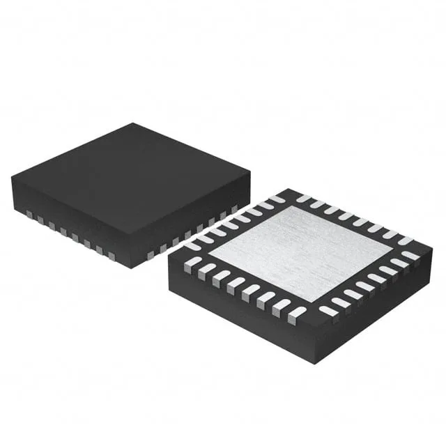
1.2A peak / 600mA continuous — the current split that decides the load
The L2293QTR is a quad half-bridge driver from STMicroelectronics, built for inductive loads: DC motors, relays, solenoids, and bipolar stepper motors. The headline numbers are 1.2 A peak per channel and 600 mA continuous — the gap between them matters because the peak rating covers the inrush when a motor starts or a solenoid pulls in, while the continuous figure governs steady-state running. If your load draws 800 mA after the start transient, this part derates below that; the continuous 600 mA per channel is the ceiling for sustained operation. The four half-bridge outputs can be configured as two full H-bridges for two DC motors or one H-bridge plus a bipolar stepper driver. The interface is simple ON/OFF logic — no PWM step/direction input, no microstepping table on-chip. That keeps the BOM cost low but puts the commutation sequencing on the host MCU.
Supply range and thermal envelope
Both the logic supply and the load supply share the same 2.8 V to 36 V window — one rail powers everything. That covers 5 V logic and 12 V or 24 V industrial motor buses from a single regulator. The junction temperature range is -20°C to 125°C, which fits factory-floor enclosures and outdoor telecom cabinets but stops short of the -40°C cold crank required for under-hood automotive. If the board sees -30°C at a wind farm site, the L2293QTR is outside its rated operating band. The datasheet's RthJA figure assumes a certain pad size — a layout without those vias will hit the overtemperature shutdown earlier than the 1.2 A peak suggests. That protection is the only fault safeguard on-chip; there is no undervoltage lockout or cycle-by-cycle current limit, so the supply rail must be stable and the load current must stay within the SOA.
Active lifecycle — no EOL clock ticking
The L2293QTR is the Tape & Reel variant of the L2293Q, which ships in Tray. The die and electrical specs are identical — the only difference is the packaging format. If your pick-and-place line is set up for reels, the QTR suffix is the one to order; if you have a prototype run or a small batch, the tray version (L2293Q) avoids the reel minimum quantity. Both are active and cross-reference directly at the footprint level.