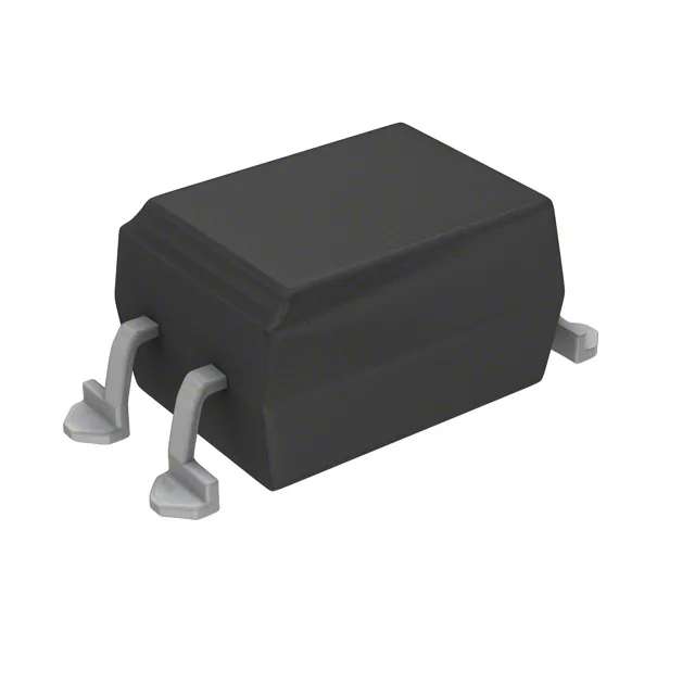
Vishay SFH6106-3T — Optoisolators

SFH6106-3T Optoisolator, 5300Vrms, 100-200% CTR

MPNSFH6106-3T
End of Life

Vishay SFH6106-3T optocoupler, 1-channel DC-input transistor output, 5300Vrms isolation, 100-200% CTR at 10mA, 4-SMD Gull Wing package, surface mount, -55 to 100°C.

$0.97Ref. price · indicative, final on quote
Packaging4-SMD, Gull Wing
StockContact for availability
MOQ1 pcs
  • 100% new & originalTraceable channels only — no refurbs, no pulls, no remarked parts.
  • Date & lot codes on quoteStated per line before you commit; label photos on request.
  • MSL-compliant ESD packingMoisture-sealed bags with indicator cards; reels photo-verified.
  • PayPal buyer protectionPay by T/T, PayPal or Payoneer — card payments covered end to end.

Specifications

SFH6106-3T Technical Specifications
ParameterValue
Input typeDC
Output typeTransistor
Mounting typeSurface Mount
Voltage - isolation5300Vrms
Voltage - output70V
Voltage - forward (Vf)1.25V
Current - output (Channel)50mA
Current transfer ratio200% @ 10mA
Current - DC forward (If)60 mA
Operating temperature-55°C ~ 100°C
PackageTape & Reel (TR); Cut Tape (CT)
Case4-SMD, Gull Wing
Number of channels1
Vce saturation400mV
Rise (Fall time)2µs, 2µs
Turn on (Turn off time)3µs, 2.3µs

Product details

5300 Vrms reinforced isolation in a 4-SMD gull-wing package

The Vishay SFH6106-3T is a single-channel phototransistor optocoupler in a 4-SMD gull-wing package rated for 5300 Vrms isolation — a reinforced-insulation grade suitable for separating high-voltage and low-voltage domains in power supplies, motor drives, and industrial I/O modules. The DC input side drives an IR LED (typical forward voltage 1.25 V, max continuous forward current 60 mA), and the phototransistor output handles up to 70 V at 50 mA per channel. The -3 CTR bin (100% to 200% at 10 mA forward current) sits between the -2 and -4 gain tiers, giving a predictable drive margin for logic-level coupling without overloading the output side.

CTR bin -3: what the 100–200% range means for your design

The current transfer ratio (CTR) of 100% to 200% at 10 mA forward current defines how much collector current the phototransistor can sink for a given LED drive. At the minimum 100% CTR, 10 mA in gives at least 10 mA out — enough to saturate a TTL or CMOS input with margin. The 200% ceiling means the same input can drive a higher-impedance load without needing a separate gain stage. The -3 bin is the most commonly specified mid-range gain for general-purpose isolation; if your load requires less than 5 mA output, the -2 bin (63–125%) saves LED drive current, while the -4 bin (160–320%) handles degraded LED output over temperature or lifetime.

Switching speed and timing budget

Typical rise and fall times are 2 µs each, with turn-on time of 3 µs and turn-off time of 2.3 µs. That puts the usable switching frequency around 50–100 kHz for digital isolation — adequate for status feedback, relay drivers, and isolated serial links at moderate baud rates. The 400 mV Vce(sat) maximum at rated collector current keeps the output drop low enough to drive 3.3 V logic directly.

Temperature range and environment

Rated for -55°C to 100°C operating temperature, the SFH6106-3T covers industrial and some automotive under-hood environments. The 5300 Vrms isolation withstands transient overvoltages in mains-powered equipment; the 4-SMD gull-wing package is compatible with standard reflow soldering profiles (MSL level not stated, but typical for this package family is MSL 1).

Frequently asked questions

What is the current transfer ratio (CTR) of SFH6106-3T?

The CTR range is 100% to 200% at 10 mA forward current. This is the -3 bin, a mid-gain selection between the -2 (63–125%) and -4 (160–320%) options in the SFH6106 family.

Can SFH6106-3T be replaced by SFH6106-2T?

The SFH6106-2T is pin-compatible and shares the same package and isolation rating, but its CTR bin is 63–125% at 10 mA. If your circuit was designed for the -3 bin's 100–200% range, the -2T may not provide enough output current at the same LED drive — verify the minimum load current before substituting.