What this buck controller brings to a power stage
The UCD7230RGWT is a single-phase step-down (buck) controller from Texas Instruments, built for non-isolated point-of-load regulators where efficiency and switching speed matter. It drives an external transistor pair — the synchronous rectifier is integrated on the controller side, so you get the conduction benefit without the external diode drop. Switching frequency goes up to 2 MHz, which lets you shrink the magnetics and output cap but demands careful layout to keep the switch-node loop tight. Operating temperature covers -40 °C to 125 °C junction — industrial gear, telecom base stations, and under-hood electronics that see 105 °C ambient still have margin before the thermal shutdown bites.
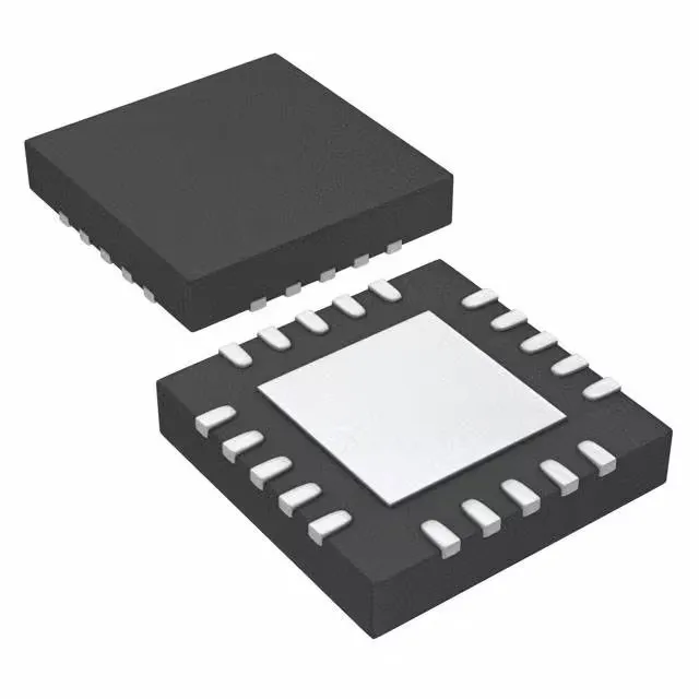
Housed in a 20-VQFN with exposed pad (5x5 mm body). The thermal pad underneath is the primary heat path — solder it to a copper plane with enough vias to pull the heat into the inner layers. The exposed pad also serves as the ground return for the power stage, so the via count and placement affect both thermal and electrical performance. Surface-mount only, supplied on tape and reel or cut tape. The 0.5 mm pitch demands a solder-paste stencil aperture that matches the pad dimensions in the TI land pattern — too much paste and you risk bridging between the thermal pad and signal pins.
Control features and what they mean for the loop
Current-limit and enable pins are on the controller. The current-limit threshold is set by an external resistor — you size it for the inductor saturation current plus a margin for the transient response. Enable lets you sequence the rail on and off without an extra supervisor IC. No clock-sync input, so the switching frequency free-runs at the value set by the RT resistor. If you need to synchronize multiple rails to a common clock to beat beat-frequency noise, this part won't do it — look at the UCD7xxx family with SYNC pin instead.