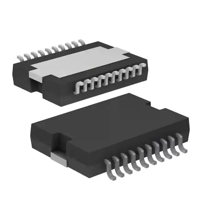
Dual LDO with adjustable and fixed output options
The STMicroelectronics L4938EPD13TR packs two positive LDO regulators in one PowerSO-20 package — one rated for 100 mA output, the other for 400 mA. The primary channel is adjustable up to 5.1 V max, while the second is fixed at 5 V, giving you a mixed-rail solution for powering a 5 V logic rail alongside a lower-voltage analog front-end or sensor bias.
Dropout voltage and thermal performance
The dropout voltage is 0.4 V max on the 100 mA channel and 0.6 V max on the 400 mA channel — tight enough that a 5 V output stays regulated with an input as low as 5.6 V. Over-temperature protection is built in, so if the load spikes or ambient climbs, the regulator shuts down rather than letting the silicon cook.
Control logic and enable sequencing
Both channels have an Enable pin, and there is a shared Reset output — useful for sequencing: hold the Enable low until the input rail is stable, then release; the Reset pin flags when both outputs are within regulation.
The exposed pad is the main thermal path — the board layout should mirror the pad with a grid of vias to an inner ground plane.
No direct pin-compatible second-source is listed, but the dual-output configuration is uncommon enough that a board spin would be needed to substitute.