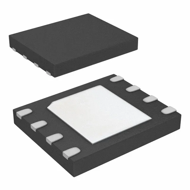
Micron Technology MT25QL128ABA1EW9-0SIT TR — Memory (DRAM / SRAM / Flash / EEPROM)

Micron MT25QL128ABA1EW9-0SIT TR 128Mbit NOR Flash, 133 MHz SPI

MPNMT25QL128ABA1EW9-0SIT TR
End of Life

Micron MT25QL128ABA1EW9-0SIT TR, 128Mbit NOR Flash, SPI - Quad I/O, 133 MHz, 2.7V-3.6V, -40°C to 85°C, 8-WDFN exposed pad, Tape & Reel.

$4.07Ref. price · indicative, final on quote
Packaging8-WDFN Exposed Pad
RoHSROHS3 Compliant
Independent supplier — new & surplus stockAuthenticity-screened · ESD-safe packingListing updated Aug 2026

Specifications

MT25QL128ABA1EW9-0SIT TR specifications
ParameterValue
Memory typeNon-Volatile
MountingSurface Mount
Voltage2.7V ~ 3.6V
Frequency133 MHz
Memory interfaceSPI - Quad I/O
Operating temperature-40°C ~ 85°C (TA)
PackageTape & Reel (TR); Cut Tape (CT)
TechnologyFLASH - NOR
Memory size128Mbit
Memory formatFLASH
Case8-WDFN Exposed Pad
Memory organization16M x 8
Write cycle time - word, page8ms, 2.8ms

Product details

Clocked at 133 MHz, the part operates from 2.7 V to 3.6 V and is rated from -40°C to 85°C.

Write timing — page and word program cycles

Page program time is 2.8 ms typical; word program time is 8 ms typical.

No end-of-life notice or last-time-buy schedule is in effect.

Frequently asked questions

Is MT25QL128ABA1EW9-0SIT TR obsolete or end-of-life?

No, the MT25QL128ABA1EW9-0SIT TR is listed as Active in production and ROHS3 compliant. No end-of-life notice is in effect.

Are there equivalents or replacements for MT25QL128ABA1EW9-0SIT TR?

The MT25QL128ABA1ESE-0SIT TR is a functional peer with the same 128 Mbit density, 133 MHz clock, and SPI Quad I/O interface, but in a different package variant. For automotive-grade requirements, the MT25QL128ABA8ESF-0AAT TR offers AEC-Q100 qualification and an extended temperature range up to 105°C.

What is the pinout of MT25QL128ABA1EW9-0SIT?

The pinout is defined in the Micron MT25QL128ABA datasheet. The 8-WDFN package uses standard SPI pins (CS#, CLK, SI, SO) plus the Quad I/O pins (IO2, IO3) and power/ground. The exposed pad is the ground reference and should be soldered to the PCB ground plane.