What the PLL and 1:21 ratio mean for your clock tree
The W312-02HT integrates a phase-locked loop (PLL) that takes a single crystal reference and synthesizes up to 21 differential clock outputs at frequencies up to 248 MHz. The 1:21 input-to-output ratio means one crystal feeds the entire clock tree — no need for multiple oscillators or a separate fanout buffer. Two independent PLL circuits let you generate two distinct frequency domains from the same crystal — for example, a 100 MHz core clock and a 66 MHz peripheral bus, each with its own output bank. The differential outputs are typically LVDS or LVPECL — the exact standard is not specified in the listing, but the differential pair routing on the PCB must be impedance-controlled (100 Ω differential for LVDS) and length-matched to within the receiver's skew budget.
Supply rails and temperature — the fit constraints
The device requires two supply rails: a core supply of 2.375 V to 2.625 V and an I/O supply of 3.135 V to 3.465 V. Both must be present and within tolerance — a missing or out-of-spec rail will prevent the PLL from locking. This part is not qualified for industrial (-40°C to +85°C) or automotive environments. If the end system sees ambient below freezing or above 70°C, this is the wrong device.
RoHS non-compliance — the sourcing reality
For any BOM that must meet EU RoHS, China RoHS, or similar regulations, this part cannot be used without an exemption.
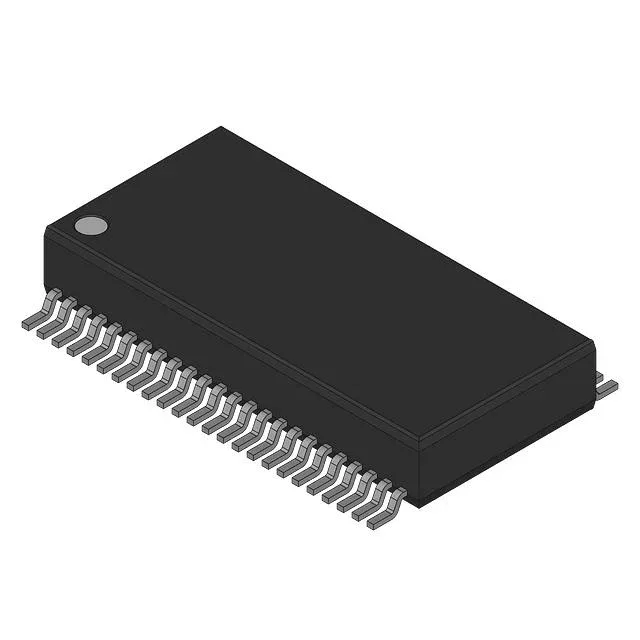
The W312-02HT comes in a 48-lead BSSOP package with a 0.295-inch body width and 7.50 mm width. The supplier device package is listed as 48-SSOP — these are the same footprint. Mounting is surface-mount. The package is supplied in bulk, not tape-and-reel — plan for manual or tray-fed pick-and-place, not reel-fed assembly.