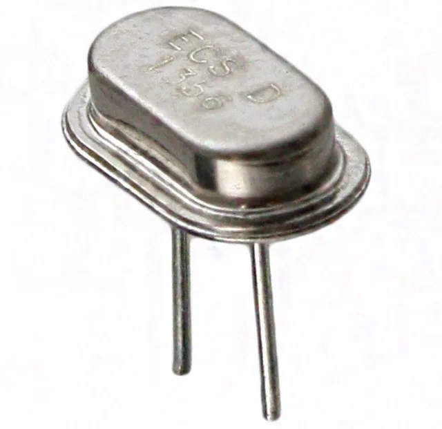
Frequency budget: stability vs tolerance
The ECS-130-20-46X: The ±50 ppm frequency stability encompasses temperature drift over the rated -10°C to 70°C window — it is the number that governs how far the crystal wanders in the field. The ±30 ppm tolerance is a one-time production offset at 25 °C; the two add in opposite directions, so the worst-case initial deviation is 80 ppm, but temperature does not compound the tolerance once the unit is trimmed. ESR is listed at 60 Ω — that is the motional resistance the oscillator loop must overcome at startup. For most microcontrollers with integrated Pierce oscillators, a 60 Ω ESR at 13 MHz sits within the drive-level budget, but if the chip's oscillator is marginal at the high-ESR end of the tolerance band, swapping to a lower-ESR variant improves startup margin. Load capacitance of 20 pF is the standard choice for consumer microcontroller families — the Pierce oscillator's two external caps (C1, C2) are sized as CL minus the microcontroller's pin capacitance. A 20 pF crystal with 15 pF caps gives 7.5 pF effective load, which pulls the oscillation frequency slightly above series resonance; check the MCU datasheet to confirm whether the oscillator is specified for parallel or series resonant operation, since the wrong cap choice shifts the frequency by several ppm.
HC-46/X footprint — what it connects to
The through-hole leads pass through the board and are wave-soldered or hand-soldered from the bottom side, which means the crystal sits proud of the PCB surface by roughly 1.8 mm. For dense two-layer boards with tight component spacing, confirm the seated height clears tall adjacent parts. Operating mode is fundamental — the crystal vibrates at its first overtone, not at a multiple. Some MCUs with high clock frequencies (above ~25 MHz) require overtone crystals, but at 13 MHz the fundamental is the correct choice and the Pierce oscillator will lock reliably without an external matching network.