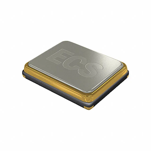
12.288 MHz — the timing anchor that locks UART and telecom clocks
The ECS-122.8-8-33-JGN-TR: 12.288 MHz is a power-of-two baud-rate crystal: 12.288 MHz ÷ 384 = 32 kHz, and it divides cleanly to all common UART rates (115200, 57600, 9600) without fractional-N rounding error — which is why it appears in Bluetooth modules, GSM basebands, and any wireless SoC that derives its serial clock from a reference divider chain. The ±30ppm total tolerance (stability plus tolerance combined) meets the Bluetooth LE and 802.15.4 maximum frequency error budget of ±40 ppm for the RF section and ±50 ppm for the baseband UART — the two specs typically drive the tolerance selection for a wireless design, not either one alone. Load capacitance is 8 pF. The crystal does not pull itself — the load capacitors on the PCB (typically C0G/NP0, 10–22 pF each) set the actual resonant frequency in-circuit, and the 8 pF figure tells the layout engineer to target a total external capacitance of roughly 16 pF including parasitic trace capacitance to close the tolerance budget.
4-SMD no-lead package at 3.20×2.50×0.80 mm
The 4-SMD no-lead package in a 3.20×2.50 mm body with 0.80 mm seated height is the ECX-32 series footprint — compatible with the standard pads on BLE and sub-GHz module reference designs, so the crystal drops onto most wireless SoC evaluation boards without layout spin. Fundamental-mode operation means the crystal runs at its series-resonance fundamental, not an overtone — no matching network or harmonic trap is needed, and the ESR of 100 Ω is the full-load ESR the drive circuit must source. Crystal drive level is typically limited to 100 µW; exceeding it shifts frequency and shortens life.
Active part — sourcing posture and BOM fit
The ECX-32 series covers the same 3.2×2.5 mm footprint across a wide frequency range, so a frequency-shift within the family can be a second-source hedge if the exact 12.288 MHz line tightens. Confirm the reel-vs-cut-tape packaging with your EMS — cut tape suits low-volume NPI runs, full reel suits volume placement. The 100 Ω ESR is a watch item for the crystal drive circuit; if your SoC's external crystal driver is marginal at startup, budget a lower-ESR alternative in the BOM risk register.