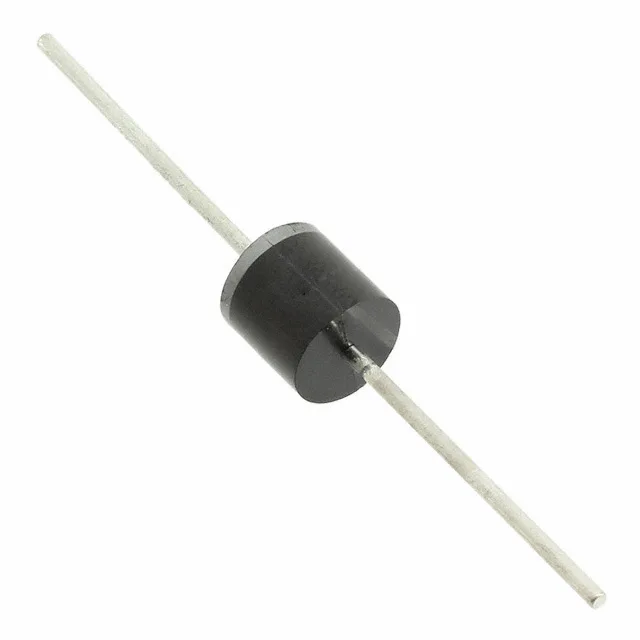
The 5KP22CA-G: At this waveform the clamping voltage sits at 35.5 V max at a peak pulse current of 140.85 A. A 5 kW device in R-6 axial package is typically deployed at the board entry point on 24 V power rails, protecting downstream ICs from EFT and surge events that exceed the downstream supply's absolute-maximum rating. The reverse standoff of 22 V sets the normal operating bias — the TVS stays in high-impedance mode and does not conduct until the transient pushes the line above 24.4 V breakdown.
Single-channel unidirectional — clamping direction matters
One bidirectional channel sounds like it handles both polarities, but in TVS nomenclature a bidirectional-channel count of 1 indicates a unidirectional device — it clamps one polarity only. The other polarity is protected only if the circuit ground reference naturally absorbs it or a complementary TVS is placed on the opposite rail. In a 24 VDC power path this is usually fine; in an AC-coupled signal line a unidirectional TVS will not protect negative-going transients. Confirm the clamping direction against the actual fault scenario before committing the BOM line.
R-6 axial package and through-hole mounting
R-6 axial package mounts in standard 0.025 inch lead dia holes on a 0.300 inch lead spacing — the same footprint as DO-201AD. The axial lead form factor allows heat sinking through the leads into the PCB copper; no thermal pad or exposed paddle is involved. Tape & Box packaging is the standard reel-free option for through-hole components and matches the automated axial insertion equipment common in power-supply and protection-module assembly.
The 150 °C maximum junction temperature rating places this device in the industrial/military temperature band — the upper limit is set by the junction-to-lead thermal resistance and the maximum allowable case temperature for the Zener junction. At the 5 kW peak pulse rating the transient thermal impedance matters: repeated high-energy pulses close together can accumulate junction heat. For a continuous 24 V rail with infrequent surge events the temperature margin is adequate; for a motor drive output stage with repetitive transients the designer should check the pulse-derating curve in the Comchip datasheet before committing to full load. The -55 °C low end covers cold-start and outdoor equipment deployment.