64 MHz Cortex-M0+ — throughput for control loops and sensor fusion
The STM32G030K6T6: The ARM Cortex-M0+ core runs at 64 MHz, delivering the single-cycle multiply and tightly coupled interrupt controller that matter for real-time control loops. For a motor commutation loop or a sensor fusion filter running at 10 kHz, the 64 MHz clock leaves headroom for the application stack without pushing the core to its ceiling. 32 KB of on-chip Flash and 8 KB of SRAM define the firmware and data budget. A typical HAL plus RTOS footprint leaves roughly 12-16 KB for application code and 4-5 KB for stack and heap — enough for a PID controller with data logging or a Modbus slave node.
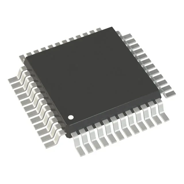
32-LQFP (7x7 mm) — board footprint and pinout constraints
The 32-LQFP package with a 7x7 mm body and 0.80 mm pitch is a two-layer-board-friendly footprint. The 30 I/O lines break out to the outer rows without via-in-pad, so a simple 2-layer PCB with ground plane pours on both sides handles the fan-out.
Analog and connectivity — 16-channel ADC, I²C, SPI, UART, LINbus
The 16-channel 12-bit ADC samples up to 1 Msps — enough for reading six thermistors and two current-sense resistors in a 100 µs window. The connectivity set includes I²C, SPI, UART/USART, and LINbus, so the part serves as a sensor hub or a fieldbus slave node without external protocol chips. Peripherals include DMA, I²S, POR, PWM, and WDT. The DMA offloads ADC result transfers from the core; the PWM timers generate complementary outputs with dead-time insertion for half-bridge motor drives.