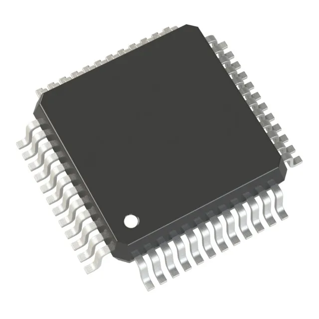
100 MHz Cortex-M4 with 128 KB flash — memory and throughput budget
The STM32F410CBT3: That flash-to-RAM ratio — 4:1 — suits control loops where the code image is modest but the interrupt stack and DMA buffers need room. The 128 KB program memory holds a full HAL plus a moderate application layer without external flash; the 32 KB SRAM leaves about 8-12 KB for the stack and heap after the RTOS and driver footprint, so budget the linker map before committing to this part for a data-heavy design. The 100 MHz ceiling is the core clock, not the bus clock — the AHB and APB domains run at derived dividers. For timing-critical peripherals like the 12-bit ADC (10 channels) or the PWM timers, the actual sample rate and resolution depend on the clock tree configuration, not just the core speed.
For USB or CAN applications where a precise time base is required, an external crystal can still drive the HSE input — the internal RC is accurate enough for UART baud rates and general-purpose timing.
Peripheral set and I/O budget
36 GPIOs in a 48-pin package — subtract the power, ground, oscillator, and reset pins, and the usable I/O count is around 28-30 depending on the peripheral mux configuration. No USB or CAN peripheral on this variant — if either is required, the STM32F411 or STM32F413 siblings add those interfaces at the cost of a larger package and higher pin count. On-chip peripherals include DMA (for memory-to-peripheral transfers without CPU load), PWM timers (for motor control or LED dimming), a watchdog timer, brown-out detect, and power-on reset. These reduce the external component count — a single MCU can handle the control loop, supervisory functions, and communication without a separate supervisor IC or external PWM controller.