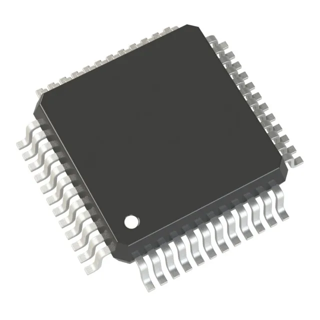
The STM32F302C6T6 runs an ARM Cortex-M4 core with single-precision FPU at 72 MHz. That clock rate and the DSP extensions mean it handles real-time control loops with floating-point math — motor FOC, digital power conversion, or sensor fusion — without an external DSP coprocessor. On-chip memory is 32 KB flash and 16 KB SRAM. For a typical field-oriented control application, the firmware image for the control loop, commutation tables, and communication stack fits within 32 KB; the 16 KB SRAM holds the state variables and a modest data buffer. If the application needs more than that, step up to the 64 KB or 128 KB flash variants in the same package.
48-LQFP package — reflow and board-fit check
No exposed pad, so the thermal path is through the leads only — keep the trace width to each pin adequate for the 3.6 V supply rail current. The package is tray-shipped; if your pick-and-place feeds from tape, confirm the tray-to-tape transfer with your CM.
Vcc range is 2.0 to 3.6 V. ROHS3 compliant — no restricted-substance issue for EU or global shipments. Production status is active, so no end-of-life risk for current designs.
Peripheral set and connectivity
The part includes DMA, I²S, POR, PWM, and WDT. The 11-channel 12-bit ADC and single 12-bit DAC cover analog signal chain — current sensing, temperature measurement, or analog output. Connectivity includes CAN, I²C, IrDA, LIN, SPI, UART/USART, and USB. For a motor-drive application, the CAN and SPI handle fieldbus communication while the PWM timers drive the inverter stage. 37 general-purpose I/O pins are available in the 48-pin package. That is enough for a keypad, a small character LCD, and a few status LEDs alongside the serial interfaces.