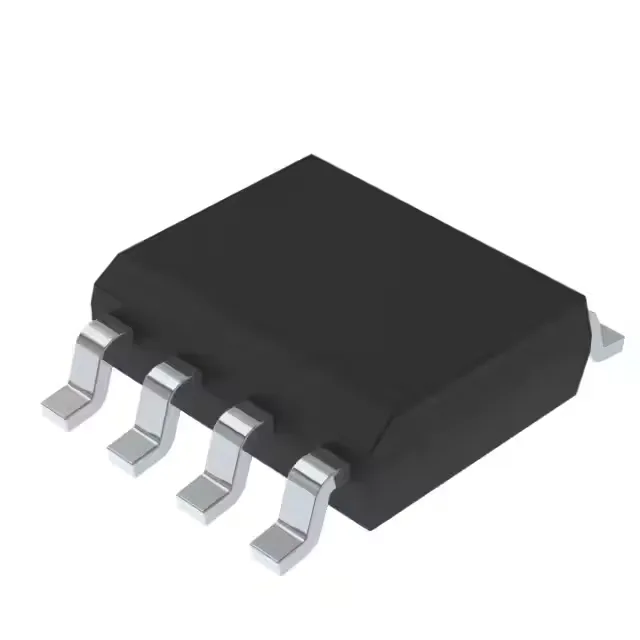
5V rail regulation for mixed-signal boards
The KF50BD-TR is a 5V fixed-output linear regulator from STMicroelectronics, delivering 500 mA from a 20V maximum input rail. It sits in the 8-SOIC footprint — a standard body width of 0.154 inches — and is specified for the -40°C to 125°C operating range, covering both industrial and under-hood ambient conditions without a separate heat sink at this current level. The 1 mA quiescent current is modest for a 500 mA LDO — useful on always-on rails where the regulator's own draw enters the system power budget.
PSRR profile and noise rejection
Power-supply rejection ratio is 76 dB at 120 Hz, rolling off to 60 dB at 10 kHz. The 120 Hz figure is the key number for rectified line-frequency ripple — a full-wave rectified 50/60 Hz supply produces 100/120 Hz ripple, and 76 dB of rejection knocks a 1 Vpp ripple down to roughly 160 µV at the output. Above 10 kHz the rejection drops to 60 dB, still attenuating switching-regulator noise from a pre-regulator by 1000:1. For a mixed-signal board where an analog front-end shares a 5V rail with digital logic, this PSRR curve means the LDO cleans up the bulk of the line-frequency ripple, but high-frequency noise above 100 kHz passes through with less than 20 dB of attenuation — a ferrite bead or pi filter ahead of the LDO is worth considering if the pre-regulator switches above 200 kHz.
Protection and control — what the enable pin buys you
The enable pin (active-high, referenced to the regulator ground) lets a supervisor IC or a GPIO pull the output to zero without disconnecting the input rail.
No exposed thermal pad — the junction-to-ambient thermal resistance is carried through the lead frame and the copper traces on the PCB. For 500 mA output with a 5V dropout (input at 10V, output at 5V, 2.5W dissipation), the board needs at least 1 oz copper and a 1-inch-square copper pour on the top layer to keep the junction below 125°C in still air. At lower dropout the dissipation drops proportionally. The enable pin is pin 2 on the standard 8-SOIC pinout — pull it high to the input voltage for always-on operation, or drive it from a logic signal. The output capacitor should be a 10 µF ceramic with at least 10V rating; the LDO is stable with ESR up to a few ohms, so a low-ESR MLCC works without an external series resistor.
The packaging options — Tape & Reel (TR) for automated pick-and-place or Cut Tape (CT) for prototype builds — give the procurement desk flexibility without changing the die or the footprint. The same 8-SOIC layout accepts either packaging variant.