45 V rail protection — what the standoff, breakdown, and clamping ratings mean
The 1.5SMCJ45A_R1_00001: The 45 V reverse standoff is the working rail this part guards — it sits idle below that voltage and begins conducting only when the transient pushes it past the 50 V minimum breakdown threshold. That 5 V margin between standoff and breakdown gives the clamping stage room to respond before the protected rail sees the fault. When the transient fires, the clamping stage clamps at 72.7 V maximum with a 20.6 A peak pulse current on the industry-standard 10/1000 µs waveform — this is the 1500 W peak pulse rating playing out in real clamping action. The 72.7 V ceiling is what the downstream bus sees during the event, so the downstream rail's transient-withstand rating must clear that number comfortably. The 1.5 kW peak pulse rating is sized for the 10/1000 µs test wave — raising the event energy (shorter, sharper surge) will push the clamping voltage higher before the TVS self-protects; check the Vc vs Ip curve in the Panjit datasheet if the application surge profile differs from the standard test condition.
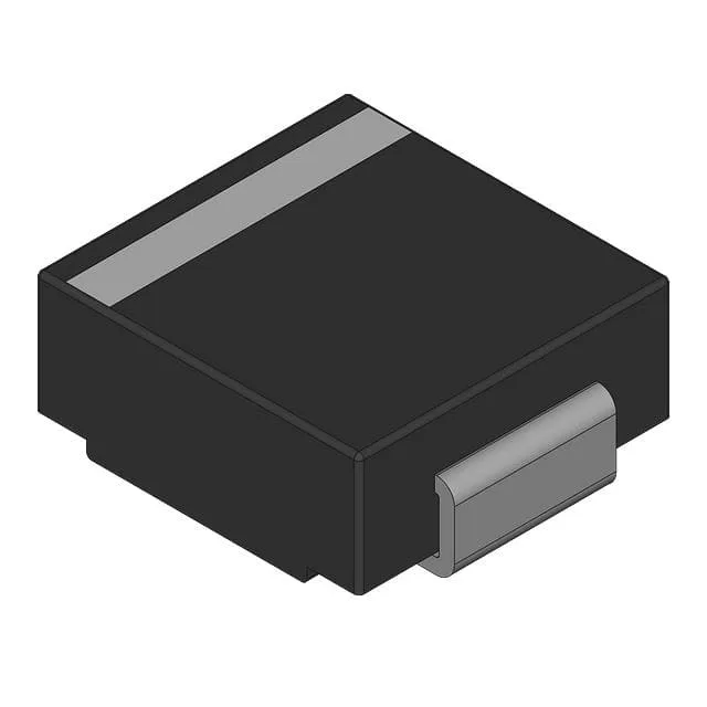
The DO-214AB (SMC) package is the standard TVS footprint — board layout follows the same land pattern used across the 1.5SMCJ series, so pin-compatible alternatives within the family are drop-in candidates. Junction temperature rated to 150 °C with a floor of -55 °C — the wide window covers automotive under-hood ambient swings and industrial enclosures that run hot in summer without derating the peak pulse rating, assuming the PCB thermal design keeps the junction below 150 °C under the worst-case sustained fault.
Marked Active by Panjit International Inc. — this part is in normal production and supported for new design-in. Tape & Reel and Cut Tape packaging options support both high-volume SMT assembly and low-quantity prototype reels. Lead time and lot traceability are confirmed per order.