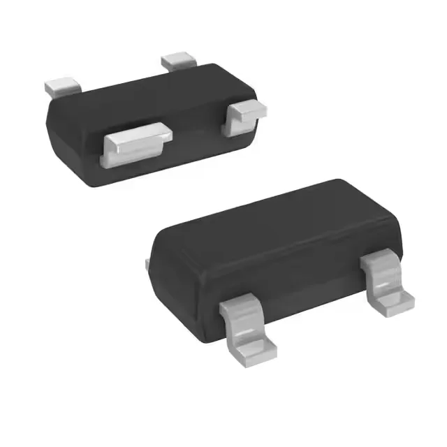
AEC-Q101 RF transistor for 900 MHz front-ends
The BFU520R is an NPN silicon RF transistor in the automotive-qualified BFU520 family, AEC-Q101 Grade 1 rated for junction temperatures from -40°C to 150°C. This means it survives the thermal cycling and peak under-hood temperatures of an engine-bay ECU or a transmission-mounted telematics unit — the same die that goes into a base-station LNA gets the automotive screening and PPAP documentation. The headline RF specs are a 10.5 GHz transition frequency and a 0.65 dB noise figure at 900 MHz. In a 900 MHz ISM-band receiver (think tire-pressure monitor, keyless entry, or a cellular NB-IoT front-end), that NF sets the cascaded noise floor — every 0.1 dB of NF you save at the LNA buys you about 0.1 dB of link margin at the demodulator. The 20 dB gain at the bias point (20 dB typ at 5 mA, 8 V) is enough to swamp the mixer noise figure in a single-stage superhet chain.
Bias point and thermal budget in SOT-143B
The 450 mW max power in the SOT-143B package is the thermal ceiling. At 5 mA and 8 V the transistor dissipates 40 mW — well within the limit — but if you bias for higher linearity at 30 mA and 12 V (360 mW), the junction temperature rise above the 150°C absolute max becomes the constraint. The SOT-143B has a collector pad on the back side; the PCB ground-plane copper area under that pad directly sets the thermal resistance. A 1 cm² copper pour on a 2-layer board drops RthJA by about 40% vs a minimal pad.
Active production, automotive supply chain
Sourced through authorized and independent distribution channels. Pricing and lead time are confirmed at RFQ against the BOM quantity. The part is available in Tape & Reel (TR) or Cut Tape (CT) packaging for the SOT-143B footprint.