What the voltage and current ratings mean for a single-rail design
The MP28200GG-Z: The input window is 2 V minimum to 5.5 V maximum — that puts it squarely in the single-cell Li-Ion/Li-Po band, with enough headroom to run from a 5 V rail or a USB bus directly. Output is adjustable from 0.8 V up to 3.3 V, which covers the core voltages on most 3.3 V logic, low-power MCUs, and wireless modules — but it cannot generate a 5 V rail, so it is not a general-purpose post-regulator for everything downstream. 200 mA continuous output is modest; it is sized for locally decoupled rails on a board that already has a higher-current front-end converter, not for driving motors, LEDs, or anything that pulls sustained bulk current.
Synchronous rectification and the 1.5 MHz switching choice
The synchronous rectifier replaces the external catch diode with an internal FET — eliminating the diode forward drop at 200 mA saves 100–150 mW of dissipation compared to a non-synchronous buck, which is meaningful when the total output is only 660 mW at 3.3 V. 1.5 MHz switching lets the inductor and output caps shrink — for a 200 mA design you can get away with a 4.7 µH inductor and 10 µF ceramic output, keeping the regulator within a 2×2 mm footprint without chasing the switching node across the board.
12-QFN package — thermal pad is not optional
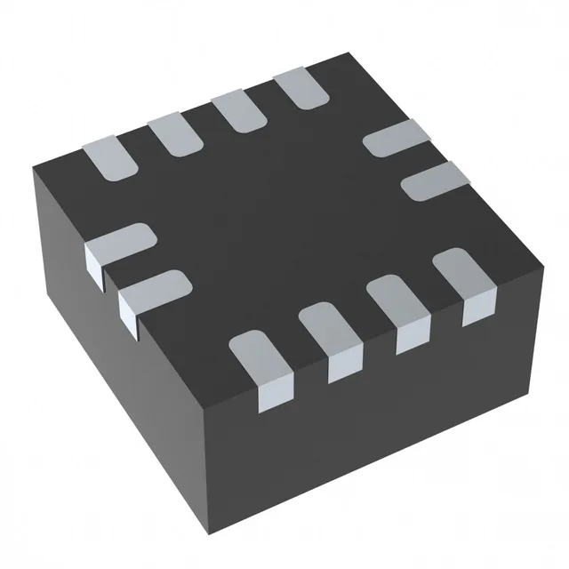
The 12-QFN (2×2 mm) is a thermally enhanced package — the exposed paddle under the device is the primary heat-removal path, not the leads. It must be soldered to a properly thermal-via'd pad on the board; a floating pad or insufficient vias will push the junction temperature above the rated 125 °C under even modest load. Surface-mount only, supplied on tape-and-reel or cut tape — no through-hole variant, so the board must support reflow assembly.
Active production, ROHS3 — what the compliance status gives you
The part carries an Active product status and ROHS3 compliance — it is in normal production and suitable for new designs without qualification risk on the basic environmental directive. No official successor or second-source cross-reference appears in the manufacturer record for this specific order code. A parametric family search within the same series is the first step if you need a replacement pin-compatible option.