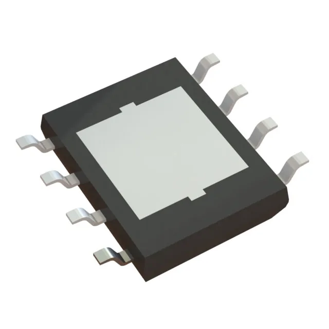
PG-DSO-8-43-EP footprint and board integration
The BTS50901EJAXUMA1: The 0.154-inch body width and 3.90mm height are standard SOIC-8 dimensions, but the exposed pad adds a center land that the layout needs to accommodate — the solder paste stencil aperture for the pad should be about 50% coverage to avoid voids. No special MSL handling is flagged in the record, but the exposed pad means the part should see a reflow profile that hits the pad joint temperature — typically 260°C peak for lead-free.
90mOhm Rds(on) and the load current ceiling
The Rds(on) rises with temperature; at 125°C junction the resistance roughly doubles, so the actual voltage drop across the switch at 3A is closer to 0.54V than the 0.27V at 25°C. Budget the thermal rise from the PCB copper area, not just the package. The 3A maximum continuous output current is the DC limit — the part can handle higher pulsed currents for short durations, but the datasheet's SOA curve (not in this record) defines the pulse-width limits. For a resistive load like a lamp or solenoid, the inrush current at turn-on may exceed 3A for milliseconds; the fixed current-limiting fault protection clamps the output to a safe level during that event.
5V to 28V load range and the On/Off interface
The voltage range across the load switch is 5V to 28V, which covers standard automotive battery rails (12V nominal, 24V truck systems) and industrial 24V supplies. The input-to-output ratio is 1:1, meaning the switch passes the load voltage straight through when enabled — no step-up or regulation. The On/Off interface is a logic-level input that turns the N-channel FET on or off; no external Vcc supply is needed because the gate drive is powered from the load voltage itself. The high-side configuration means the switch sits between the positive supply rail and the load — the load connects to ground. This is the standard topology for driving lamps, relays, solenoids, and small motors in automotive and industrial panels, because a fault on the load side (short to ground) is safely interrupted by the switch opening.
Fault protection suite for robust operation
The BTS50901EJAXUMA1 integrates current limiting (fixed), open load detection, over-temperature shutdown, and over-voltage clamping. The current limiting is fixed — it does not need an external resistor to set the threshold — which simplifies the BOM but means the limit is not adjustable. Open load detection flags a disconnected load by sensing the output voltage when the switch is off; this is useful for diagnostics in safety-critical circuits like brake lights or valve actuators. Over-temperature protection shuts the switch off when the junction exceeds the thermal shutdown threshold (typically 150°C to 175°C, per the PROFET family behavior). The part auto-restarts after the die cools, which protects against sustained overloads but can cause pulsed operation in a fault condition — the downstream load sees repeated on-off cycles until the fault clears.
The 150°C TJ max is the absolute limit — the actual case temperature at full load will be lower depending on the PCB copper area and airflow. For a 3A continuous load in a 85°C ambient, the junction temperature rise above the ambient is roughly 50°C to 70°C with a 1-inch² copper pad, keeping the junction under 150°C.