24.576 MHz timing — what the ppm numbers actually mean
The ECS-245.7-20-5PVX: The 24.576 MHz frequency is a standard clock crystal for UART baud-rate generation — 24.576 MHz divided by 16 yields the 1.8432 MHz base clock that standard 8250/16550 UARTs multiply up to standard baud rates with zero error. If you are designing in a UART or any bit-clock derived from a crystal divisor, this frequency is not arbitrary; it is the clean solution to the baud-rate error budget. ±30 ppm is the initial tolerance at 25 °C; ±50 ppm is the total frequency stability across the operating temperature range of -10°C to +70°C. For a UART running at 115200 baud, a ±50 ppm crystal introduces a worst-case baud error of 0.0058% — well within the ±2% margin most UARTs tolerate. For a precision timing reference, however, you need to account for both contributions: the initial offset and the temperature drift sum to the full ±50 ppm budget, not just one or the other.
Load capacitance and ESR — the circuit-side selection check
The 20 pF load capacitance matches what most microcontrollers specify for their crystal pins — the crystal is specified at this load, meaning the total capacitance on each crystal leg (including PCB trace capacitance and MCU pin capacitance) should sum to 20 pF for the crystal to oscillate at its rated frequency. Stray capacitance on a typical two-layer board runs 4–8 pF, so a crystal specified at 20 pF load typically needs external load caps in the 10–15 pF range to hit the correct total — confirm this against your MCU's crystal circuit recommendations. ESR is specified at 40 Ω maximum. A higher-than-expected ESR can cause startup failures in low-power oscillator circuits, particularly if the MCU's oscillator drive strength ismarginal. For a 24.576 MHz fundamental crystal at 40 Ω ESR, the drive-level power is well within the typical 1 mW limit for HC-49/US crystals — this part will start reliably in standard MCU oscillator circuits.
HC-49/US package — the footprint reality check
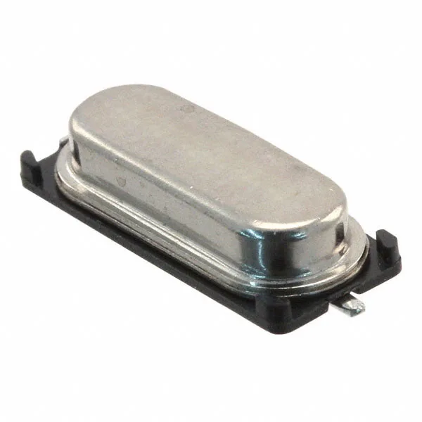
This is the taller, higher-frequency variant of the classic HC-49 can — the 'US' suffix designates the low-profile but still-through-hole friendly profile. It mounts surface-mount, not through-hole; the leads bend to sit flat on the PCB pad. The 11.40 mm length is the dimension that typically catches designers — verify your PCB layout clears this length before committing to the footprint. Packaged on tape-and-reel or cut-tape. Surface-mount orientation for automated pick-and-place is standard. If you are reworking by hand or hot-air, the HC-49/US is one of the more forgiving packages — the metal can acts as a heat sink, so preheat the board to avoid thermal shock cracking the crystal element.