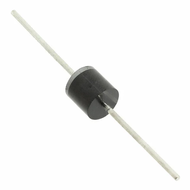
5 kW peak pulse — what the clamping window means for the design
The 5KP170A-G: The 170 V standoff sets the normal operating rail the protected circuit sees; when a transient exceeds the 189 V breakdown minimum, the TVS clamps the spike to 275 V, dumping up to 18.18 A through the protection path. For a 170 V rail, that clamping headroom of roughly 100 V above standoff is the margin the designer budgets against inductive kick and lightning-surge transients per IEC 61000-4-5.
Junction temperature range and the axial package in context
Tape & Box packaging is standard for through-hole TVS diodes — the axial leads are bent and formed to the R-6 outline, then banded into strips for auto-insertion. For a repair or rework board, hand-soldering the leads is straightforward; the body is non-moisture-sensitive (no MSL rating applies to axial glass-bodied diodes), so dry storage is not a concern the way it is for plastic SMD packages.
General-purpose classification and what it means for cross-ruffling
The 5KP170A-G is classified General Purpose — no medical, automotive, or Hi-Rel screening flows on the base part. For a new design requiring 5 kW peak pulse at 170 V standoff, the part fits a standard procurement lane; for an existing board spin or repair BOM, the R-6 axial pinout and 170 V standoff voltage are the matching parameters.