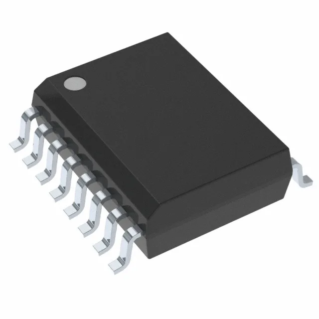
The ADUM1401ARWZ: Pin 1 is marked by a dot on the top of the package; the orientation is unambiguous under a microscope or automated optical inspection. The 2.5 ns typical rise/fall time means the output edges are fast enough for 1 Mbps signalling but not so aggressive that they ring badly on a poorly terminated trace. If your board sees fast common-mode spikes from an IGBT bridge, this part holds its output state through them.
Channel count and direction — what the 3/1 input split means
Four unidirectional channels, arranged as three on side 1 and one on side 2. That 3/1 split is the difference between the ADUM1401 and the ADUM1400 (which is 2/2). For a typical isolated SPI bus — three signals from the controller (SCK, MOSI, CS) and one back (MISO) — this channel map matches without wasting a channel. Propagation delay is 100 ns max in either direction, with 40 ns max pulse-width distortion. At 1 Mbps (1 µs bit period), the delay eats 10% of the bit window — fine for most UART or low-speed SPI links, but if you are running near the data-rate ceiling you need to budget that skew into the timing closure. The magnetic coupling technology means no LED ageing or current-transfer-ratio drift over temperature — the propagation delay stays stable from -40°C to 105°C, which is the full operating range listed.