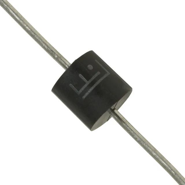
The 5KP15A-AT/B: The 209 A peak pulse current tells you the clamping headroom: when the transient hits, the TVS conducts that current at the clamping voltage, shunting energy away from the downstream IC. A lower clamping voltage means less overstress on the protected rail, and 24.4 V max at Ipp is the ceiling your load must survive.
The protection window: standoff, breakdown, and clamping
The reverse standoff voltage of 15 V is the working DC rail the TVS sees in normal operation — it sits off and draws only leakage current. When a transient pushes the rail above the 16.7 V minimum breakdown, the Zener characteristic turns on and the TVS enters its clamping region. For a 12 V automotive rail, that window gives plenty of margin; for a 24 V system the standoff is the limiting factor and the design needs to account for the full transient spectrum.
Junction temp is the metric, not ambient — derate accordingly for your thermal path from leads to ambient.
P600 axial package and through-hole assembly
The P600 axial body sits on 0.4-inch lead spacing — it mounts perpendicular to the board in a standoff configuration, which helps the leads dissipate the 5 kW pulse energy without overheating the package. Through-hole reflow or wave-solder is the standard assembly route; the axial lead form factor is forgiving on thermal mismatch compared to a surface-mount part of the same power class. Verify your board hole size and pad diameter match the P600 land pattern — the body is physically larger than a SMD TVS and needs clearance.