TVS clamping and the 376 V rail it protects
The 1.5KE440CA/B: Its 376 V reverse standoff voltage means it sits across a nominal 376 VDC bus without conducting leakage current, then clamps transients at 602 V maximum to protect downstream silicon. The 418 V minimum breakdown voltage gives the guard band: a 376 V rail that sees a 10 % overvoltage to 414 V still stays below the avalanche threshold, so the diode does not wear from repetitive micro-breakdown events.
At the clamping voltage of 602 V, the diode conducts 2.5 A peak pulse current (Ipp) for the standard 10/1000 µs surge. That 2.5 A figure is the current the part must survive once — not a continuous rating, but the single-pulse energy the junction absorbs before the TVS clears the transient. The 1500 W peak pulse power is the product of clamping voltage and peak current at that test condition. For shorter pulses (8/20 µs), the peak current capability is higher; the 10/1000 µs waveform is the conservative industrial benchmark used for AC line and DC bus protection.
DO-201 axial package and board integration
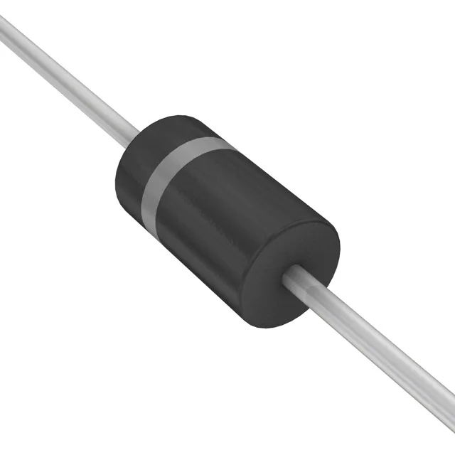
Housed in a DO-201AA (DO-27) axial-lead package, the 1.5KE440CA/B mounts through-hole. The DO-201 body handles the thermal pulse of a 1500 W surge without cracking the epoxy — the lead frame and die attach are sized for the energy, not just the steady-state dissipation. The junction temperature rating is the limiting factor for repetitive surge applications — derate the peak pulse power above 25 °C per the thermal impedance curve in the full datasheet.
Lifecycle and supply posture
No power line protection rating is assigned — this TVS is intended for signal and DC bus clamping, not for direct AC mains primary protection where coordinated fusing and MOVs are required.