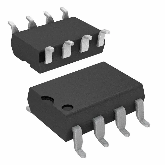
TLP250H(TP1,F) - Toshiba Semiconductor and Storage
X36 PB-F DRIVER COUPLER 8 GULL W
Full Technical Specifications
16 Parameters| Parameter / Attribute | Specification / Value |
|---|---|
| Input type | DC |
| Output type | Push-Pull, Totem Pole |
| Mounting | Surface Mount |
| Supply voltage | 10V ~ 30V |
| Voltage - isolation | 3750Vrms |
| Voltage - forward (Vf) | 1.57V |
| Current - output (Channel) | 2.5 A |
| Current - DC forward (If) | 20mA |
| Operating temperature | -40°C ~ 125°C |
| Package | Tape & Reel (TR) Cut Tape (CT) |
| Case | 8-SMD, Gull Wing |
| Channels | 1 |
| Inputs - side 1/Side 2 | 1/0 |
| Rise (Fall time) | 50ns, 50ns |
| Propagation delay tpLH (tpHL) | 500ns, 500ns |
| Common mode transient immunity | 40kV/µs |
Need Stock or a Drop-in Second-Source for TLP250H(TP1,F)?
Package: DIP-8 (gate-drive optocoupler) · Pin-compatible replacements with immediate Shenzhen spot stock
This eight-pin row is how inverter, servo and welder drive boards cross the isolation barrier to fire their IGBTs: TLP250 from Toshiba, HCPL-3120/A3120 from the Avago lineage, FOD3120 from the Fairchild line - four houses, one socket, and a repair literature that swaps them by name. The selection axis is output current (TLP250 at a 1.5A peak against the 2.5A class of its successors) and input threshold (the 3120 triggers from a lower LED current), and the design axis is the negative gate rail that keeps Miller capacitance from re-triggering the IGBT. In repair, the row behaves; what re-fails is the rail and the bypass capacitor the procedure keeps forgetting.
Verified Pin-Compatible Replacements (3 verified alternatives)
The Documented Upgrade in the Same Socket
Shenzhen Spot Stock (24-48h Dispatch)
The higher-output member: about +/-2.5A peak against the TLP250s +/-1.5A, aimed at 1200V IGBTs in the 20-100A class, with lower supply current - the direct upgrade path of the row.
Gate-side supply in the 10-35V class; isolation 2500V class.
The Other House of the Same Socket
Shenzhen Spot Stock (24-48h Dispatch)
The Avago-line drive optocoupler: about +/-2A output, direct drive of 150A/1200V IGBT modules, and a lower LED threshold (about 2.5mA) that changes the input-side resistor arithmetic.
15V to 30V gate-side supply; isolation 1414V class (the HCNW variant carries the higher figure).
The Fairchild-Line Member
Shenzhen Spot Stock (24-48h Dispatch)
The Fairchild-line drive optocoupler with the 2.5A-class output: functionally the TLP350 of the row in the onsemi lineage.
Same gate-side envelope as the row.
Buyer & Quality Checklist for Sourcing Alternatives
- The negative gate rail is the design, not the luxury: a VEE below emitter (the +15/-15V or +15/-8V schemes) prevents Miller-capacitance false turn-on in bridge drives. Repairs that skip the negative rail reintroduce the shoot-through the original design existed to avoid.
- The bypass capacitor lives between pins 8 and 5 (0.1uF class) - it is in every application note and on no repair checklist; missing it turns switching transients into mysterious drive glitches.
- Crossing houses recomputes the input resistor: Toshiba members trigger around 5mA, the 3120 family around 2.5mA - the difference is the LED and eventually the driver behind it.
- Output current is the power-class axis: 1.5A against 2.5A peaks decides whether the part drives the IGBT gate directly or leans on a post-amplifier stage - read the schematic, not the name.
- When a drive optocoupler fails, the IGBT usually failed first (or together): meter the gate-emitter junction and the collector path before fitting the third driver into the same board.
- In repair inventory, the row is one drawer with one trap: isolation grade differences (HCNW and wide-body variants) mean the subs that exist on paper are not always subs on the board.
Frequently Asked Technical Questions
Q: Can TLP250 and HCPL-3120 replace each other?
A: In low-power drives yes - the reported practice is direct interchange in the 8-pin socket - with the input-resistor recomputation for the different LED thresholds (about 5mA against 2.5mA). In mid and high-power drives compare the output-current class first.
Q: What drives TLP250 output current selection?
A: The IGBT gate charge and the absence of a post-amplifier stage: 1.5A peaks suit the 50A/1200V class the TLP250 was specified for, while the 2.5A members (TLP350, FOD3120) cover 20-100A modules without help.
Q: Why do repaired inverter drives fail again at power-up?
A: Commonly the negative gate rail or the missing bypass capacitor: without VEE the Miller capacitance false-triggers the bridge, and without the 0.1uF at pins 8-5 the drive sees every switching transient. Check both before blaming the new optocoupler.