350 mA load ceiling and on-resistance floor
The AQY225R1SZ switches 350 mA through the load at up to 80 V — that ceiling governs whether the relay handles the downstream actuator or indicator circuit, not the headline voltage rating. At 350 mA through 1.2 Ω max on-state resistance the conduction loss sits around 150 mW, which the 4-SOP body dissipates without a heatsink in free air at typical board temperatures. The RF output designation (AC, DC (RF)) means the off-state isolation holds across a frequency band — relevant for mixed-signal or RF signal routing, not just DC load switching. A bare electromechanical relay does not carry that rating.
1.14 VDC input drive and logic-level compatibility
The input LED drive is specified at 1.14 VDC — a GPIO pin or low-voltage MCU output can forward-bias the optocoupler LED without an intermediate driver, provided the port can supply the typical LED current (in the 5 mA range for this series). Confirm the MCU pin current drive against the series LED Vf curve at the operating temperature. Because the input is a pure LED — no logic-level threshold to hunt — the turn-on voltage margin is the gap between the 1.14 VDC nominal and whatever the MCU rail actually sits at. A 3.3 V rail gives comfortable headroom; a 1.8 V rail may not reach the guaranteed LED current without a pull-up or driver stage.
4-SOP footprint and surface-mount assembly
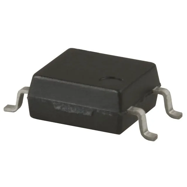
The 4-SOP (0.173 inch, 4.40 mm) package with gull-wing termination is a standard SMD footprint — the same body width used across the PhotoMOS AQY family, which means the land pattern is interchangeable within the series. Verify pad stack-up and solder mask dam for rework access; gull-wing leads on a 4.40 mm body are accessible with a fine-tip iron. Tape-and-reel packaging (TR) with cut tape (CT) option covers both high-volume SMT placement and low-quantity prototyping runs — specify CT for one-off board bring-up to avoid a full reel.