Topology flexibility and the 50% duty-cycle limit
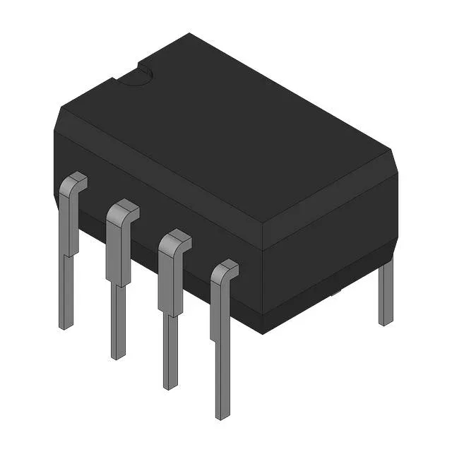
The MIC38C44YN: This controller supports boost, buck, flyback, and forward topologies from a single die — one BOM line covers multiple isolated or non-isolated power supply designs. The 50% maximum duty cycle is the hard ceiling: in a buck converter the step-down ratio is limited to Vout/Vin ≤ 0.5, and in a boost the step-up ratio is capped at 1/(1-0.5) = 2×. For higher ratios you need a different controller or a two-stage approach.
Switching at 500 kHz — magnetics and thermal trade-off
The 500 kHz oscillator lets you shrink the transformer or inductor core size compared to a 100 kHz design — useful when board space is tight. The penalty is higher switching losses in the external MOSFET and more drive current from the Vcc rail.
Supply rail and start-up behaviour
The Vcc range is 9 V to 20 V, so it runs from a regulated 12 V rail or an unregulated 15 V auxiliary winding without an external LDO. The start-up threshold is 14.5 V — the controller stays off until the supply crosses that level, then the undervoltage lockout hysteresis determines the brown-out restart point. Below the UVLO threshold the quiescent current is minimal, which matters for off-line designs that use a bleeder resistor from the bulk capacitor.
The 8-pin DIP limits the number of auxiliary functions (no sync pin, no soft-start pin), but the frequency control feature lets you adjust the oscillator with a single resistor. The through-hole body sits above the board, so the thermal resistance to ambient is higher than a surface-mount SOIC with a copper pad; plan for a heatsink if the junction temperature approaches 150°C.