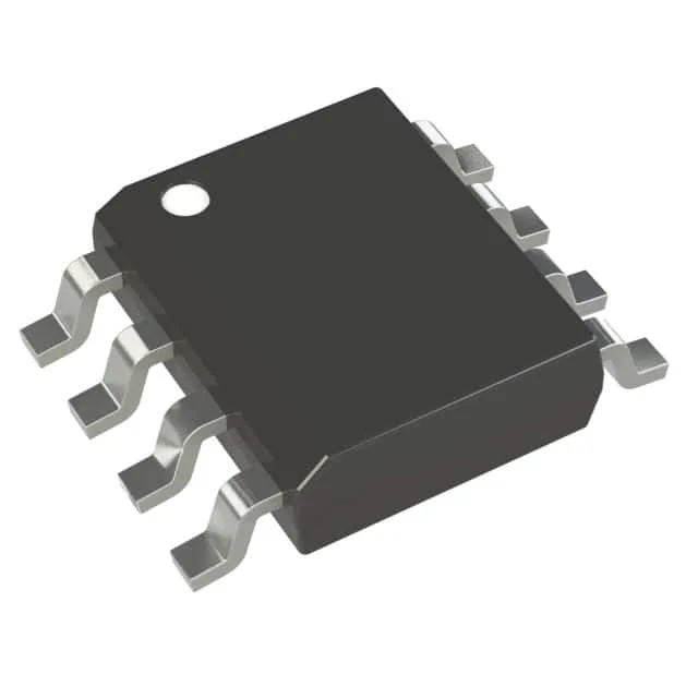
Microchip Technology MCP14A0303T-E/SN — Power Management (PMIC / Gate Driver)

Microchip MCP14A0303T-E/SN IGBT Gate Driver, 3A Peak, 8-SOIC

MPNMCP14A0303T-E/SN
End of Life

Microchip Technology MCP14A0303T-E/SN dual IGBT gate driver, 3A peak source/sink, 12ns rise/fall, 4.5V-18V supply, inverting input, 8-SOIC package.

$1.14Ref. price · indicative, final on quote
Packaging8-SOIC (0.154", 3.90mm Width)
Independent supplier — new & surplus stockAuthenticity-screened · ESD-safe packingListing updated Aug 2026

Specifications

MCP14A0303T-E/SN specifications
ParameterValue
Gate typeIGBT
Input typeInverting
Channel typeIndependent
MountingSurface Mount
Voltage4.5V ~ 18V
Logic voltage - VIL, VIH0.8V, 2V
Current - peak output (Source, sink)3A, 3A
Operating temperature-40°C ~ 125°C
PackageTape & Reel (TR); Cut Tape (CT)
Case8-SOIC (0.154\", 3.90mm Width)
Number of drivers2
Driven configurationHigh-Side or Low-Side
Rise (Fall time)12ns, 12ns

Product details

Dual 3A IGBT driver in a standard SOIC footprint

The MCP14A0303T-E/SN is a dual-channel gate driver rated for 3 A peak source and 3 A peak sink current — symmetrical drive that charges and discharges the IGBT gate capacitance at the same rate, so the turn-on and turn-off delays stay matched within a few nanoseconds. Rise and fall times are 12 ns typical into a 1 nF load, which means the driver can switch a standard IGBT module's input capacitance in under 30 ns without lingering in the Miller plateau region where the gate voltage stalls. The inverting input logic and the 4.5 V to 18 V supply range let this part sit between a 5 V PWM controller and a 15 V IGBT gate rail — no level-shifting buffer needed.

Supply rails, temperature grade, and board-fit

No derating curve to worry about in a motor-drive enclosure that sees 85°C ambient or an outdoor solar inverter cabinet. Each of the two channels operates independently — they share only the supply and ground pins. Paralleling both channels for a single 6 A peak drive is possible if the PCB trace impedance is balanced, but the datasheet layout recommendation should be followed to keep the gate loop inductance below 10 nH.

Frequently asked questions

What is the closest functional second-source to MCP14A0303T-E/SN?

Neither MIC4104YM nor TC4424EPA is a drop-in replacement. MIC4104YM is a half-bridge driver with non-inverting inputs and 2 A peak output. TC4424EPA is a through-hole low-side driver with non-inverting inputs and 3 A peak. Both would require schematic changes — different input polarity and, in the MIC4104 case, a different drive architecture.