70 MIPs in a 5V 16-bit DSC — what that buys the control loop
The Microchip dsPIC33EV32GM102-I/SO is a 16-bit digital signal controller that executes at 70 MIPs from its internal oscillator, which puts it ahead of the 32 MHz ceiling common on the PIC24 family. That instruction throughput matters when the control loop needs to sample an ADC, run a PID, and update a PWM period inside a single switching cycle — motor drives and digital power supplies are the natural fit.
Peripheral set: CANbus, Motor Control PWM, and DMA
This part integrates a CANbus controller, which saves the external CAN transceiver interface cost in automotive body electronics or industrial fieldbus nodes. The Motor Control PWM peripheral includes dead-time insertion and fault inputs, so it can drive a three-phase inverter bridge directly. DMA moves ADC results to RAM without core intervention, keeping the 70 MIPs budget available for the application code rather than data shuffling. The 11-channel 10/12-bit ADC samples synchronously with the PWM triggers, which is the standard architecture for sensorless BLDC control.
Memory and package — sizing the firmware and the board
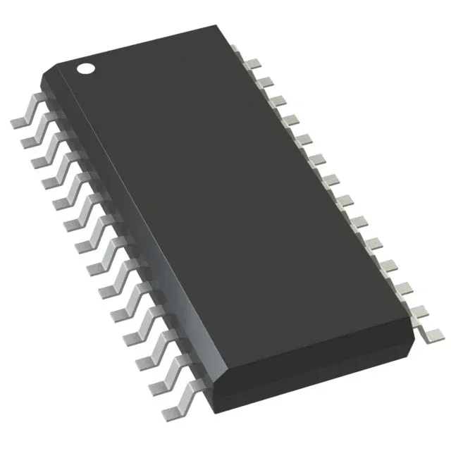
Program memory is 32 KB of Flash organized as 11K x 24-bit words, with 4K x 8 of SRAM. That is enough for a moderate motor-control firmware stack with CAN communication, but not for a full GUI or data-logging application — those would step up to the 64 KB or 128 KB Flash variants in the same 33EV family. The 28-pin SOIC package with 21 GPIO fits a compact two-layer PCB; the wide-body 7.50 mm width gives adequate clearance for high-voltage isolation creepage on the motor-drive side.