Abracon LLC ASE-25.000MHZ-L-C-T — Crystals & Oscillators

Abracon ASE-25.000MHZ-L-C-T XO, 25 MHz, CMOS, 3.3 V

MPNASE-25.000MHZ-L-C-T
Active

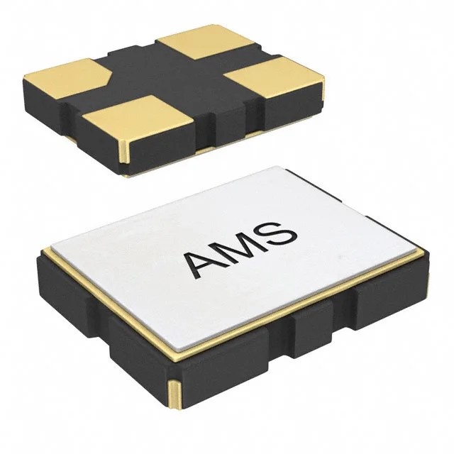
Abracon ASE-25.000MHZ-L-C-T XO (Standard), CMOS output, 25 MHz, 3.3 V supply, ±50 ppm, -40°C to 85°C, 4-SMD no-lead (3.20 mm × 2.50 mm), Enable/Disable function.

$1.0400Ref. price · indicative, final on quote
Independent supplier — new & surplus stockAuthenticity-screened · ESD-safe packingListing updated Aug 2026

Specifications

ASE-25.000MHZ-L-C-T specifications
ParameterValue
TypeXO (Standard)
SeriesASE
MountingSurface Mount
Supply voltage3.3V
Current - supply13mA
Current - supply (Disable)10µA
Frequency25 MHz
Frequency stability±50ppm
Operating temperature-40°C ~ 85°C
Size (Dimension)0.126\" L x 0.098\" W (3.20mm x 2.50mm)
Height - seated0.047\" (1.20mm)
OutputCMOS
FunctionEnable/Disable
PackageTape & Reel (TR) Cut Tape (CT)
Base resonatorCrystal
Case4-SMD, No Lead

Product details

Frequency stability and timing accuracy

The ASE-25.000MHZ-L-C-T: That translates to a worst-case timing error of ±50 µs per second, or roughly ±4.3 seconds per day — adequate for UART, SPI, and I²C clocking, USB full-speed framing, and most microcontroller PLLs that derive their core clock from it. A design requiring sub-1.5 ppm for precision timestamping or Ethernet PHY reference would need a TCXO or OCXO instead; this part carries no such qualification.

Package footprint and board integration

No exposed paddle is specified; thegnd pad under the body handles mechanical anchoring and thermal relief. Confirm decoupling topology against the datasheet — the 3.3 V rail feeding the oscillator should bequiet before the device is enabled, since the CMOS output integrity degrades if supply noise modulates the reference crystal.

Frequently asked questions

What supply voltage does the ASE-25.000MHZ-L-C-T require?

The 3.3 V level is standard for most 32-bit microcontroller families, FPGAs with 3.3 V bank supply, and USB full-speed PHYs.

What does the Enable/Disable function mean for power budgeting?

The OE pin gates the CMOS output without removing power from the oscillator circuit — the part remains biased but draws only 10 µA in disabled mode versus 13 mA active. For battery-powered devices cycling through sleep and wake states, holding the oscillator disabled during sleep preserves the differential between the two draw levels rather than requiring a full power-cycle of the rail.