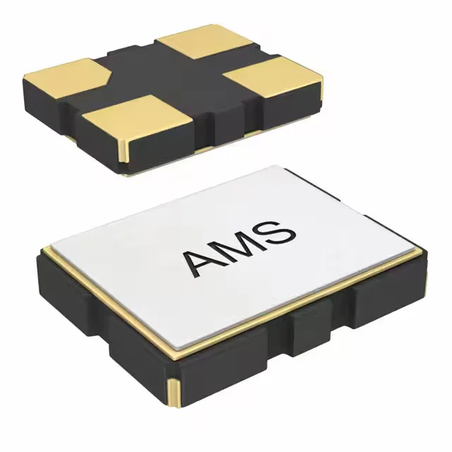
26 MHz CMOS oscillator — what the numbers mean for your timing budget
The ASE-26.000MHZ-LR-T is a standard crystal oscillator in the ASE family, delivering a 26 MHz CMOS square-wave output at 3.3 V rail. For a UART running at 26 MHz the ppm error is the dominant term in the bit-time error; 25 ppm at 115200 baud is roughly 2.8 µs of drift per hour, well within typical protocol margins. The Enable/Disable function is the feature that actually earns its place on a power-sensitive board. Supply current peaks at 13 mA when the output is toggling; in disable mode it drops to 10 µA maximum. That 1000:1 ratio lets the firmware gate the reference clock on a per-subsystem basis without physically removing the part — a sensor node that powers down its serializer between samples draws no more than the disable current from that rail while the main MCU sits in low-power sleep.
Package footprint and layout entry points
The Gull-wing or J-lead termination on a 4-SMD part sits coplanar to the board at the outer edges — reflow profile is standard SAC paste, no special soak needed for this package size. Keep the supply trace short to the oscillator and place the load capacitance or series termination close to the output pin; a long CMOS output trace acts as an antenna and reflects into the oscillator's duty cycle at the receive end. The 3.3 V supply rail should be clean at the device pin — the oscillator draws 13 mA in a 10 ns edge transition, so decoupling with a 100 pF ceramic in parallel with a 1 µF bulk bypass within 2 mm of Vdd smooths the rail during the edge. For designs that run the output into a long trace or a high-impedance input, a 33 Ω series resistor at the output pin damps reflections without degrading the CMOS rise time noticeably at 26 MHz.
Quoted to order through independent distribution against BOM quantities — availability and current lead times are confirmed at RFQ.