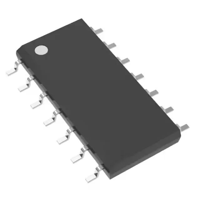
Texas Instruments SN74S05D — Memory (DRAM / SRAM / Flash / EEPROM)

SN74S05D 74S Hex Inverter, Open Collector, 20mA, 14-SOIC

MPNSN74S05D
End of Life

Texas Instruments 74S series SN74S05D hex inverter, open-collector outputs, 6 circuits, 1 input per circuit, 14-SOIC surface-mount package, 4.75V to 5.25V supply, 0°C to 70°C operating.

$1.77Ref. price · indicative, final on quote
Packaging14-SOIC (0.154", 3.90mm Width)
RoHSROHS3 Compliant
Series74S
Independent supplier — new & surplus stockAuthenticity-screened · ESD-safe packingListing updated Aug 2026

Specifications

SN74S05D specifications
ParameterValue
Series74S
Logic typeInverter
MountingSurface Mount
Supply voltage4.75V ~ 5.25V
Current - output high, low-, 20mA
I/O channels1
Operating temperature0°C ~ 70°C
PackageTube
FeaturesOpen Collector
Case14-SOIC (0.154\", 3.90mm Width)
Number of circuits6
Input logic level - low0.8V
Input logic level - high2V
Max propagation delay @ v, max CL7.5ns @ 5V, 50pF

Product details

74S Schottky hex inverter with open-collector outputs

The SN74S05D is a hex inverter from the 74S Schottky logic family, containing six independent inverter gates each with a single input. The open-collector outputs allow wired-AND connections and level shifting to higher voltages than the 5.25 V supply rail. Housed in a 14-SOIC package (0.154" width, 3.90 mm), it mounts on standard surface-mount pads and shares the footprint with other 14-pin SOIC logic devices.

Supply rails and logic thresholds

Input logic-low threshold is 0.8 V max, and logic-high threshold is 2 V min, providing direct compatibility with 5 V TTL outputs without external translation. The open-collector output sinks up to 20 mA when low (VOL), but cannot source current when high — the output floats unless pulled up externally. This is the key design constraint: a pull-up resistor to the desired output voltage is required for each gate used.

Switching speed and propagation delay

Maximum propagation delay is 7.5 ns at 5 V supply with a 50 pF load. This is the time from input crossing the threshold to output crossing the same threshold — the open-collector output's rise time is determined by the external pull-up resistor value and load capacitance, not the IC itself. For a 1 kΩ pull-up to 5 V driving 50 pF, the RC time constant adds roughly 50 ns to the rise time. Designers should budget this external delay when calculating the maximum data rate through the inverter chain.

No official successor or pin-compatible alternative is listed — the 74S family is a mature logic series. For new designs requiring open-collector inverters in SOIC-14, the 74LS05 or 74HC05 offer lower power but different switching thresholds and supply ranges.

Frequently asked questions

What does the open-collector output mean for circuit design?

The open-collector output can only sink current (pull low) — it cannot source current when the output is high. This allows wired-AND connections and level shifting to voltages above the 5.25 V supply rail, limited only by the external transistor's breakdown voltage.

What is the propagation delay and how does the external pull-up affect it?

The IC's internal propagation delay is 7.5 ns max at 5 V with 50 pF load. However, the open-collector output's rise time is dominated by the external pull-up resistor and load capacitance. A 1 kΩ pull-up to 5 V with 50 pF adds approximately 50 ns to the rise time, so the total switching time from input to valid output is the sum of the IC delay and the external RC time constant.