Clamping a 100 A surge without cooking the board
The 1.5KE11CA R0G: That 100 A peak pulse current (Ipp) at the clamping voltage means it can absorb a hefty transient — a load-dump or lightning-induced surge — without the part self-destructing, provided the energy stays within the pulse derating curve. The 9.4 V reverse standoff voltage (Vrwm) is the DC or peak-AC voltage the line normally sees; the diode stays off below that. When the transient pushes past the 10.5 V minimum breakdown voltage, the device clamps at 15.6 V maximum, shunting the surge current to ground. For a 12 V nominal rail — automotive battery, industrial control supply — this gives enough margin to avoid nuisance triggering while still catching overvoltage events.
Through-hole package and rework reality
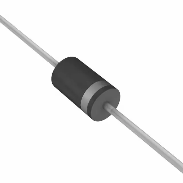
Housed in a DO-201AA / DO-27 axial-lead package, this is a through-hole part — the same footprint as the classic 1N6267 and 1.5KE series diodes. The leads are tin-plated copper; they solder cleanly into a plated through-hole with a standard iron or wave solder. No hot-air rework needed — just clip the leads, desolder the stubs, and drop in a replacement. Pin 1 is the cathode band; the bidirectional construction means polarity doesn't matter for the clamping action, but the band still marks the cathode for reference. The axial package handles the thermal cycling well — the lead frame expands with the board, reducing solder-joint stress compared to a surface-mount part in the same power class.