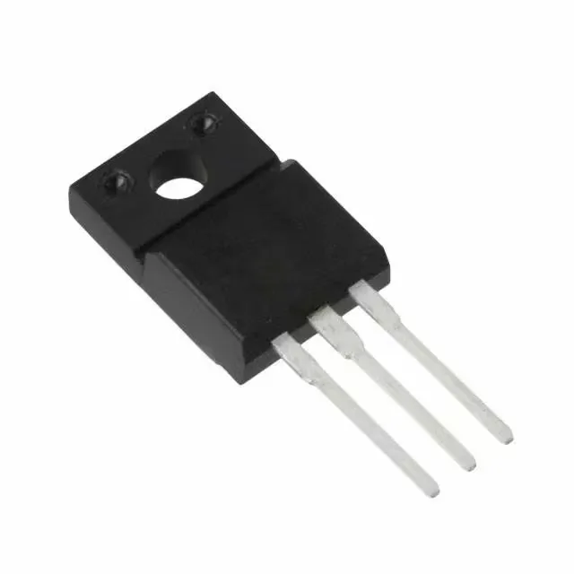
650 V, 24 A N-channel — the switching load it handles
The R6524KNXC7G: These two numbers define the primary switching load it can handle in a power supply, motor drive, or inverter stage — the 650 V breakdown gives margin on a 400 VDC bus, and the 24 A continuous rating covers the RMS current in a typical 1–2 kW offline converter.
Conduction loss and gate drive budget
Maximum on-resistance is 185 mOhm at 11.3 A drain current with a 10 V gate drive. At 24 A the Rds(on) will be higher — the 185 mOhm figure is the ceiling at the test condition, and the actual conduction loss at full load is Id² × Rds(on) × duty cycle. The 10 V drive voltage is the recommended rail for minimum Rds(on); the gate threshold is 5 V max at 750 µA, so a standard 12 V gate drive from a bootstrap or isolated supply comfortably saturates the channel. Total gate charge is 45 nC at 10 V. For a 100 kHz hard-switched converter, the average gate-drive current is Qg × fsw = 4.5 mA — a small signal driver handles it. The input capacitance is 1850 pF at 25 V Vds, which sets the switching speed limit: the driver must source and sink enough peak current to charge and discharge this capacitance within the dead time. A 1 A gate driver charges 1850 pF from 0 to 10 V in roughly 18 ns, well within a typical 100–200 ns dead band.
TO-220FM — the isolated package that bolts directly
The TO-220-3 Full Pack (also called TO-220FM) is a fully moulded through-hole package with the metal tab encapsulated — no exposed drain pad. This means the device can be bolted directly to a grounded heatsink or chassis without an insulating washer or pad, saving assembly time and reducing thermal resistance compared to a standard TO-220 with a mica insulator.
The part ships in Tube packaging.