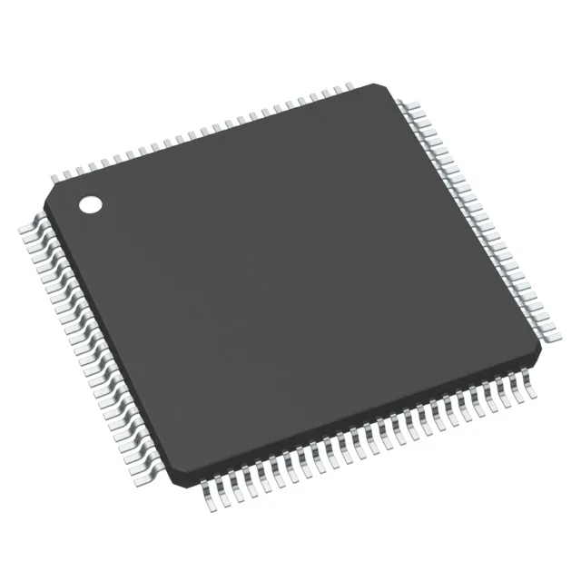
240 MHz Cortex-M33 for real-time motor control
The R7FA6T2AD3CFP#AA0 runs a 32-bit ARM Cortex-M33 core at 240 MHz — the clock rate that sets the PWM update rate and current-loop bandwidth for a motor drive. At that speed, a typical field-oriented control (FOC) loop with resolver feedback fits inside a 10–15 µs interrupt window, leaving headroom for comms stack overhead. On-chip memory is 512 KB of flash and 64 KB of RAM — enough to hold a motor-control firmware image with an EtherCAT or CANopen stack and still have room for a bootloader and parameter tables.
Analog front-end: 38 ADC channels, 4 DAC channels
The part integrates 38 channels of 12-bit SAR ADC and 4 channels of 12-bit DAC — the ADC count is high enough to sample all three phase currents plus DC-link voltage and a resolver sine/cosine pair simultaneously, without external muxing. The DACs can generate analog reference voltages or offset trim signals for external sensor amplifiers.
Peripherals for inverter control and fieldbus bridging
Hardware peripherals include DMA, PWM, LVD, POR, and WDT — the PWM timers drive the inverter gate signals directly; DMA streams ADC results into RAM without CPU intervention, keeping the core free for the control algorithm. Connectivity covers I²C, SPI, SCI, LIN, and UART/USART — enough to talk to a resolver-to-digital converter over SPI and a host PLC over CAN or serial. The internal oscillator means no external crystal is required for basic operation — the PLL locks to the internal RC and generates the 240 MHz core clock. For jitter-sensitive PWM, an external resonator can still be fed into the clock tree.
Surface-mount only. The 105°C ceiling gives margin over the typical 85°C industrial limit.
Active production, ROHS3 compliant
ROHS3 compliant, so no exemption paperwork needed for EU or UKCA markets. The RA6T2 series is positioned for motor-control and industrial inverter applications.