Dual-core architecture and the speed split that matters
The SPC5646CCF0MLT1 runs two e200z cores — the z4d at 120 MHz and the z0h at 80 MHz — which means the firmware architect can pin the real-time control loop (PWM, ADC sampling, fault handling) to the faster core and leave the comms stack (CAN, Ethernet, LIN) to the slower one without a scheduler fighting for cycles.
On-chip memory budget for a safety-oriented BOM
3 MB of program flash paired with 256 KB SRAM and 64 KB of EEPROM — the flash-to-RAM ratio is generous for an automotive MCU, so a full AUTOSAR stack plus application code fits without external memory. The EEPROM block is separate from the flash array, meaning calibration parameters survive a firmware update without a dedicated sector-erase step. Operating temperature spans -40 to 125 °C, which is the full Grade 1 automotive envelope — the silicon is characterised for under-hood ambient where the junction sees 150 °C under load. The 3-to-5.5 V supply range means it runs directly off a car battery without an intermediate regulator for the core, though the I/O ring still needs 5 V tolerant peripherals.
ADC channel count and what it covers on a sensor-heavy board
33 × 10-bit and 10 × 12-bit ADC channels — enough to sample six phases of a three-phase motor current (two per phase for redundancy) plus voltage, temperature, and position sensors without external muxing. The 10-bit bank handles fast, lower-resolution current sensing; the 12-bit bank covers the slower but more precise voltage and temperature readings.
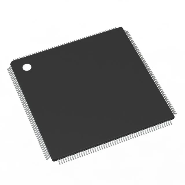
Housed in a 208-TQFP with a 28×28 mm body and 0.50 mm pitch — the footprint is standard for this pin count, so a four-layer board with a ground plane under the package handles the 177 I/O without via-in-pad. The tray packaging is the typical delivery for reflow assembly lines; no moisture-sensitive level is stated, but a 208-pin QFP at 0.50 mm pitch normally ships at MSL 3 and needs a bake if the floor life is exceeded.