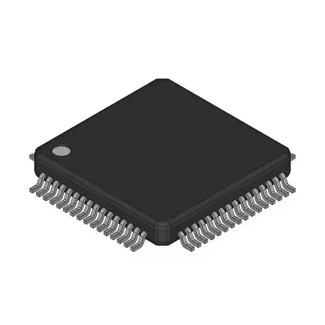
64-QFP package and board integration
The MC9S08AC32MFUE comes in a 64-QFP package with a 14x14 mm body. The 0.80 mm pitch is reworkable with a hot-air station — the leads are exposed, no hidden pads under the body, so lifting a bent pin or replacing the part is straightforward if you preheat the board from the bottom to avoid warping the QFP. Fifty-four I/O lines fan out to the perimeter — the inner rows of a 4-layer board help route the peripheral signals (I²C, SCI, SPI) without congestion. The internal oscillator saves one external crystal and two load caps, which frees up two more GPIOs for the application.
40 MHz core, 32 KB flash, and the memory budget
The S08 core runs at 40 MHz — that is the bus clock ceiling for this 8-bit architecture. For a control loop reading the 16-channel 10-bit ADC and updating a PWM output, the 40 MHz throughput is enough to close a 10 kHz current loop with margin left for the communications stack. 32 KB of flash holds the firmware image; 2 KB RAM is the working memory. The RAM budget is tight — a typical Modbus RTU buffer plus a 256-byte ADC sample queue leaves about 1 KB for the stack and local variables. Plan the data structures before committing the firmware architecture.
Industrial temperature grade and peripheral set
The LVD (low-voltage detect) and POR (power-on reset) peripherals protect against brownout conditions in noisy environments like motor drives or engine bays. The 16-channel 10-bit ADC multiplexes across the 54 I/O pins — eight of those channels can be dedicated to analog inputs without sacrificing digital I/O. The SCI module handles RS-232 or RS-485 at up to 2.5 Mbps; the SPI runs at up to 10 MHz for external ADC or DAC expansion.
No stock-holding claim — quoted to order per RFQ.