12 A RMS, 600 V — the load-switching ceiling
The NXP BTA312-600B/DG,127 is a standard triac rated for 12 A RMS on-state current and 600 V off-state voltage. That 12 A RMS figure is the continuous current the device can conduct when the junction stays at or below 125 °C — the thermal path from the TO-220AB tab to a heatsink determines how much of that rating you actually use in a given enclosure. The 600 V off-state block rating covers 240 VAC line applications with margin for mains transients up to the device's repetitive peak voltage capability. For a resistive or inductive load switched at line frequency, this part fits the standard 230/240 VAC phase-control circuit.
Surge current and inrush handling
Non-repetitive surge current is specified at 95 A for a 50 Hz half-cycle and 105 A for 60 Hz. This is the peak current the triac can survive once during its life — relevant for capacitor inrush, lamp cold-filament turn-on, or motor start transients. The 60 Hz figure is slightly higher because the shorter half-cycle deposits less energy into the die. The 60 mA maximum hold current (Ih) sets the minimum load current needed to keep the triac latched after the gate trigger is removed. Below that current the device will commutate off at the next zero-crossing — a consideration for low-current loads like small fans or indicator lamps that might drop below 60 mA during operation.
Gate drive and trigger characteristics
Maximum gate trigger current (Igt) is 50 mA, and maximum gate trigger voltage (Vgt) is 1.5 V. This is a standard-sensitivity triac — the gate drive circuit must source at least 50 mA into the gate-cathode junction to guarantee turn-on across temperature. A simple resistor-limited DC trigger from a microcontroller I/O pin may not deliver enough current; a transistor buffer or dedicated triac driver (like the MOC30xx series) is the typical interface. The 1.5 V Vgt maximum means the gate signal must rise above that threshold at the gate pin. The actual gate current delivered depends on the series resistance and the supply voltage — budget for the full 50 mA Igt over the operating temperature range, not just at 25 °C.
Package and mounting — TO-220-3 through-hole
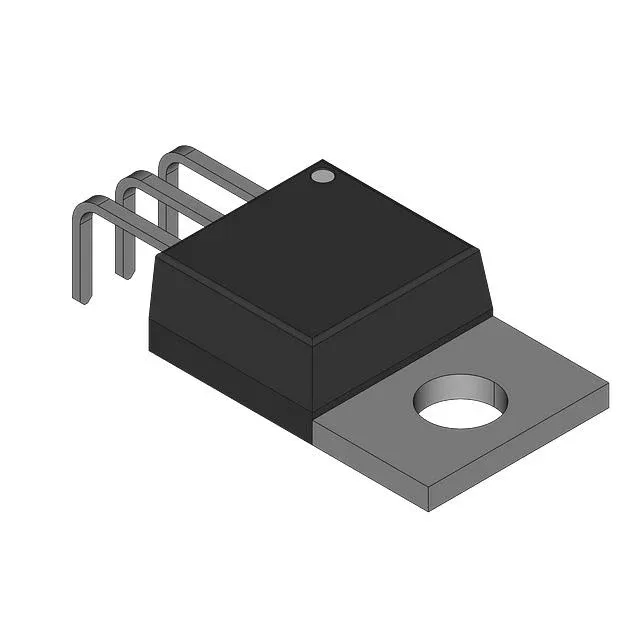
Housed in a TO-220-3 (TO-220AB) through-hole package, the BTA312-600B mounts into a standard 0.100-inch pitch hole pattern on the PCB or can be bolted to a heatsink via the integral mounting tab. The tab is electrically connected to the MT2 terminal — account for this in the heatsink isolation design if multiple devices share a common heatsink. The bulk packaging means devices ship in tubes or trays, not tape-and-reel — suitable for through-hole assembly lines with tube feeders or manual insertion. No reel quantity to track for JIT replenishment.