What the peak-pulse ratings mean for surge protection
The 5KP13CA-HRA: At that same waveform the peak pulse current is 237.2 A; the two figures are linked: the clamping voltage of 21.5 V at Ipp is what the downstream circuit sees while that current is being diverted. The 5KP-HRA sits in front of circuits that cannot tolerate a clamp above 21.5 V, so the Ipp rating confirms the part clears the fault current required to keep the clamped rail within that limit.
Standoff and breakdown — the TVS operating band
The reverse standoff voltage of 13 V sets the continuous working voltage the diode sees in normal operation — it sits off, leaking only microamps, doing nothing until a transient pushes it into avalanche. The minimum breakdown of 14.4 V is where avalanche begins; the clamping maximum of 21.5 V is the ceiling the protected load ever sees, even at full Ipp. For a board-level test engineer validating the protection loop, the key check is that the clamping voltage at the rated 237.2 A does not exceed the absolute-max input of whatever is behind it.
Wide temperature grade and axial package
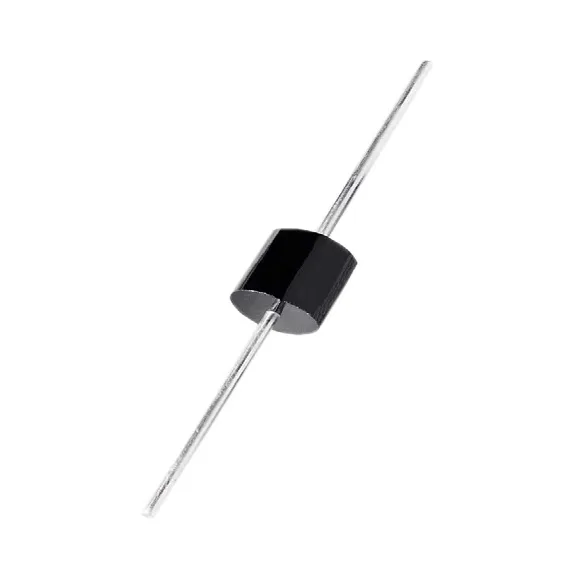
The P600 axial through-hole package mounts into a board hole pattern; lead dress and board copper area under the device determine thermal resistance from junction to ambient. For a through-hole device at 5 kW peak, the board layout matters more than the housing for thermal management during a surge event.