The Intel EPM570ZM100I8N is a MAX® II CPLD with 570 logic elements and 440 macrocells in a 100-ball TFBGA (6x6 mm), 76 user I/O. The 9 ns pin-to-pin delay (tpd1) suits address decoding and bus bridging. The -40°C to 100°C junction temperature range qualifies it for industrial gear.
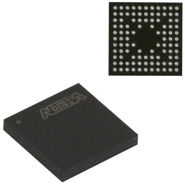
Intel EPM570ZM100I8N MAX II CPLD, 440 Macrocells, 9 ns
MPNEPM570ZM100I8N
Active
Intel MAX® II CPLD, EPM570ZM100I8N, 570 logic elements, 440 macrocells, 76 I/O, 9 ns pin-to-pin delay, 1.71V–1.89V core, -40°C to 100°C, 100-TFBGA, Tray.
$38.7000Ref. price · indicative, final on quote
Independent supplier — new & surplus stockAuthenticity-screened · ESD-safe packingListing updated Aug 2026
Specifications
| Parameter | Value |
|---|---|
| Series | MAX® II |
| Mounting | Surface Mount |
| Programmable type | In System Programmable |
| Voltage supply - internal | 1.71V ~ 1.89V |
| Operating temperature | -40°C~100°C(TJ) |
| Package | Tray |
| Number of i (O) | 76 |
| Case | 100-TFBGA |
| Number of macrocells | 440 |
| Delay time tpd(1) max | 9 ns |
| Number of logic elements (Blocks) | 570 |
Product details
Frequently asked questions
Is EPM570ZM100I8N obsolete or active?
Active. The product status is Active with no end-of-life notification. It remains available for new designs and production builds.
Where can I buy EPM570ZM100I8N available via RFQ confirmation?
This part is sourced through independent distribution and quoted to order against an RFQ. Contact us for current availability and pricing — confirmed at quote time.
What is the difference between EPM570ZM100I8N and EPM570ZM100C8N?
The suffix 'I' vs 'C' indicates the temperature grade: the 'I' version (EPM570ZM100I8N) is rated for -40°C to 100°C junction temperature, while the 'C' version is typically commercial 0°C to 85°C. The 'I' grade is the one to specify for industrial or extended-temperature applications.
What programmer is needed for EPM570ZM100I8N?
The MAX II family is In-System Programmable via JTAG. Any standard JTAG programmer that supports Altera/Intel CPLDs — such as the USB-Blaster or ByteBlaster II — works. The 10-pin JTAG header connects to TMS, TCK, TDI, TDO, VCC, and GND.
Is EPM570ZM100I8N compatible with 3.3V I/O?
Yes, the I/O banks can operate at 3.3V when the VCCIO pins are connected to 3.3V. The core runs at 1.8V, but the I/O buffers tolerate 3.3V inputs and drive 3.3V outputs. Verify the VCCIO configuration in the MAX II handbook for the specific I/O standard.