Lifecycle and BOM-fit for this MAX II CPLD
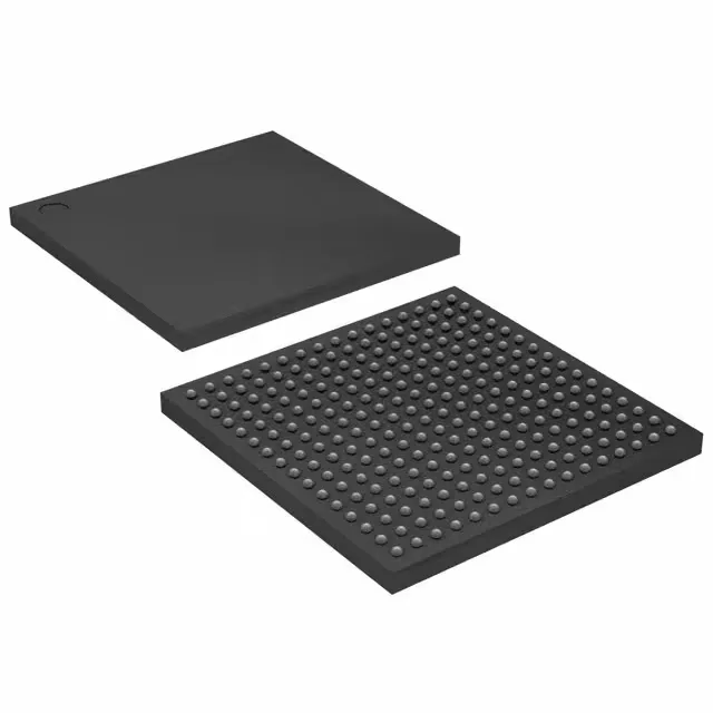
The EPM570GF256I5N: It packs 440 macrocells and 570 logic elements, with a pin-to-pin propagation delay of 5.4 ns max — fast enough for glue-logic consolidation and bus-interface decoding in systems clocked below about 90 MHz. The 160 user I/O break out to a 256-ball FBGA (17x17 mm) — the 1.0 mm ball pitch is a standard four-layer-board layout; no micro-via or HDI stack-up required.
The core supply is 1.71 V to 1.89 V — a single 1.8 V rail with ±5 % tolerance covers it, which matches the common output of a 1.8 V LDO or switching regulator. In-system programmable via JTAG, so the board can be assembled with a blank device and programmed on the line — no pre-programmed inventory to manage.
Package and board-level integration
256-FBGA (17x17 mm) with a 1.0 mm ball pitch — the fan-out uses two signal layers and a power plane; the centre 8x8 ball array is mostly VCC and GND, so a four-layer board with the core supply on an inner plane is the typical stack-up. The device ships in a tray — no moisture-sensitive reel handling; the MSL rating is not listed here, but standard MAX II devices are typically MSL 3, so a bake before reflow is prudent if the tray has been open longer than the floor life.