440 macrocells, 5.4 ns tpd — where this CPLD lands in the MAX II family
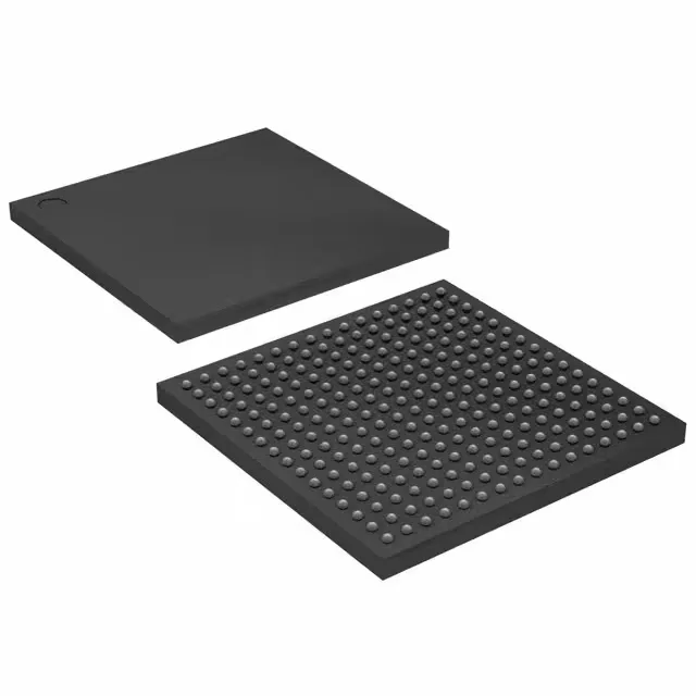
The EPM570GF256C3N is a MAX II CPLD from Intel, delivering 440 macrocells and a 5.4 ns pin-to-pin propagation delay (tpd(1) max). That tpd number is the C speed grade — the fastest available for the EPM570 density. The C3N suffix means commercial temperature range (0°C to 85°C), 1.8 V core, and lead-free (RoHS) finish. For a glue-logic design that needs to decode addresses or sequence control signals within a single 5.4 ns window, this part closes timing without adding a wait state on the processor bus. The 160 I/O pins route out of the 256-ball FBGA (17x17 mm) — enough for a 32-bit bus plus control and status lines. In-system programmability means the device can be configured after soldering, which simplifies prototype spins and field updates.
What the 5.4 ns tpd means for your timing budget
The 5.4 ns tpd(1) max is the worst-case propagation delay from any input pin through the logic array to any output pin, measured at the recommended operating conditions. For a state machine clocked at 100 MHz (10 ns period), this leaves about 4.6 ns for the external setup time of the downstream device and the PCB trace delay — tight but feasible if the board layout keeps the critical path unterminated and short. The C speed grade is one notch above the slower I grade (6.5 ns) in the same EPM570 density, so upgrading from an I-suffix part recovers 1.1 ns of timing margin without changing the pinout or PCB. Each macrocell includes a programmable register that can be configured as D or T flip-flop. The 440 macrocells break down into 570 logic elements (LEs) in the MAX II architecture — the LE count is higher than the macrocell count because each macrocell uses one LE plus routing resources. If your synthesis tool reports LUT usage, budget against the 570 LE figure, not the 440 macrocell number, because the fitter maps combinatorial logic into LEs before registering them into macrocells.
Package and board integration: 256-FBGA (17x17 mm)
The 256-ball FBGA with a 17x17 mm body and 1.0 mm ball pitch requires a 4-layer PCB minimum for fan-out — the inner layers carry the core voltage and ground planes. The device ships in a tray, not tape-and-reel, which is typical for BGA packages in this density. For high-volume pick-and-place, the tray can be transferred to a tape-and-reel carrier, but the standard ordering quantity is per tray. The 1.71 V to 1.89 V core supply means a 1.8 V rail with ±5 % tolerance is sufficient — a common LDO output like the TPS7A20 or a switching regulator with 1 % setpoint will stay within the window across load transients.