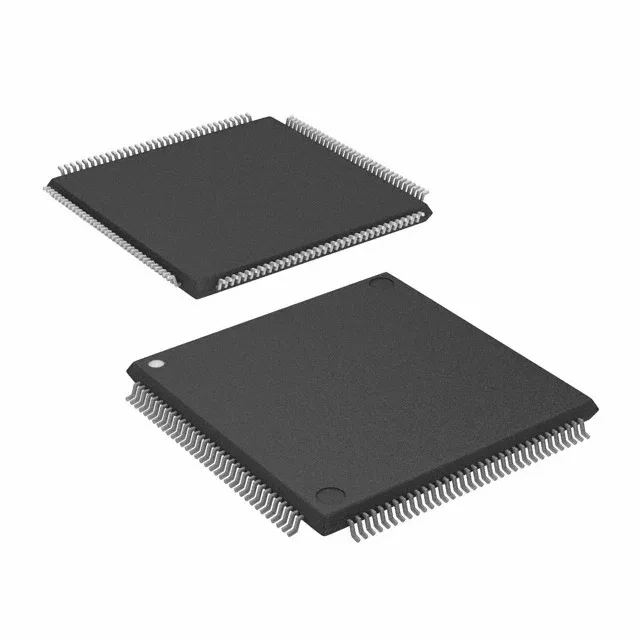
Active production — no phase-out risk for current BOMs
The EPM1270T144C3: That means it remains a safe commitment for production builds — no last-time-buy deadline to hedge, no forced migration path to budget for. For a procurement desk evaluating single-source risk, this part is still in the official supply channel.
Density and speed — where the 1270 LEs land in a real board
With 1270 logic elements and 980 macrocells, the EPM1270T144C3 sits near the top of the MAX II family — enough density to absorb a handful of 74-series glue-logic ICs, a small address decoder, a state machine, and some I/O expansion into a single 144-pin package. The 116 I/O pins give headroom for a 32-bit bus plus control signals without multiplexing. The 6.2 ns tpd(1) max delay sets the combinatorial propagation ceiling. That means a signal entering a macrocell through a registered path and exiting through a combinatorial output takes at most 6.2 ns from pin to pin. For a 50 MHz system clock (20 ns period), that leaves about 14 ns for routing, setup, and clock skew — workable for most glue-logic paths, but tight for wide fan-in combinatorial functions that cascade through multiple LEs.
Supply rails and temperature grade — the board-level constraints
The part is not single-rail; both voltages must be present on the board. The 0°C to 85°C commercial temperature range limits deployment to indoor, conditioned environments — no industrial or automotive exposure without active thermal management.
Package and programming — what the assembly line needs to know
The tray packaging means the feeder section needs a tray handler or a tube adapter; the parts do not come on tape-and-reel. In-system programmable via the JTAG interface, so a board-level firmware update does not require removing the device or using a socket adapter. The MAX II family programs with Quartus II software (version 9.1 or later) — no external programmer needed for the JTAG chain.