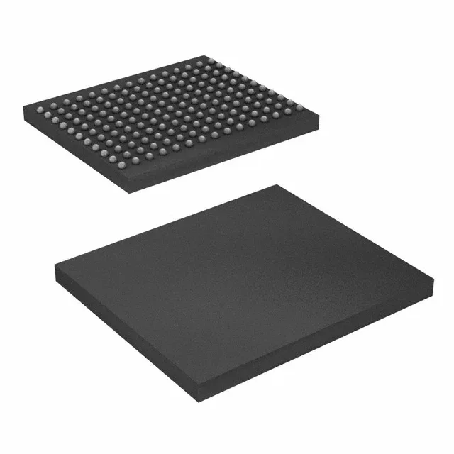
The CY7C1565KV18-500BZC: For existing BOM lines, the part is sourced through independent distribution — quantities are lot-specific and confirmed at RFQ.
500 MHz QDR II+ — the throughput ceiling
This is a 72 Mbit QDR II+ SRAM organized as 2M x 36. The 500 MHz clock rate means the device delivers a peak data rate of 2 GB/s on the read and write ports combined — each port runs at double data rate, so the internal bus width of 36 bits at 500 MHz DDR yields 4.5 GB/s aggregate bandwidth. That throughput is the deciding factor for a high-speed lookup table or packet buffer in a network line card or test equipment design where the FPGA's internal block RAM runs out. Supply voltage is 1.7 V to 1.9 V, placing it in the 1.8 V nominal QDR II+ generation. The memory interface is Parallel — the 36-bit data bus plus address and control signals require a 165-ball FBGA footprint on a board with enough routing layers to keep the trace-length-matched fly-by topology within the timing budget.
This is the commercial/industrial floor — the part is not specified for extended industrial (-40°C) or automotive environments. In a telecom central-office or data-centre switch the ambient stays within this band; an outdoor base-station or engine-bay controller would need the industrial-grade variant from the same family.
Surface-mount assembly with a standard BGA reflow profile — the 1.0 mm ball pitch on a 13x15 mm array is within the capability of most SMT lines. The supply voltage rails (1.7-1.9 V) need a dedicated 1.8 V plane with decoupling capacitors placed within 5 mm of each VDD ball to keep the transient response within the 500 MHz switching window.