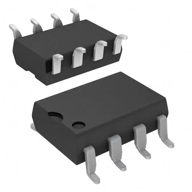
Everlight Electronics Co Ltd 6N139S(TA)
OPTOISO 5KV DARL W/BASE 8SMD
Full Technical Specifications
14 Parameters| Parameter / Attribute | Specification / Value |
|---|---|
| Input type | DC |
| Output type | Darlington with Base |
| Mounting | Surface Mount |
| Voltage - isolation | 5000Vrms |
| Voltage - output | 18V |
| Voltage - forward (Vf) | 1.3V |
| Current - output (Channel) | 60mA |
| Current transfer ratio | 500% @ 1.6mA |
| Current - DC forward (If) | 20 mA |
| Operating temperature | -40°C~85°C |
| Package | Tape & Reel (TR); Cut Tape (CT) |
| Case | 8-SMD, Gull Wing |
| Channels | 1 |
| Turn on (Turn off time) | 200ns, 1.7µs |
Need Stock or a Drop-in Second-Source for 6N139S(TA)?
Package: DIP-8 / SOP-8 · Pin-compatible replacements with immediate Shenzhen spot stock
The 6N137 is the industrial signal isolator of servo drives, PLC I/O, gate-drive interfaces and serial links: a 10 megabit logic-gate optocoupler with a Schottky-clamped open-collector output, an enable pin, and the same 8-pin body as half the opto universe. Two things make it a page of its own. First, the 6N136 it shares a family name with is a 1 megabit phototransistor part whose pins 5, 6 and 7 mean something else entirely - same body, different species. Second, the enable pin: floating it disables the output to a permanent high, which is the number one mystery of hand-wired 6N137 circuits. The 2500V isolation, ~45-75ns delays and the HCPL-2601/2611 noise-shielded versions complete the working picture.
Verified Pin-Compatible Replacements (3 verified alternatives)
The 1Mbps Phototransistor Sibling
Shenzhen Spot Stock (24-48h Dispatch)
The phototransistor version in the same 8-pin body: no VCC pin, no enable pin, CTR-based output with a base pin (7) for a speed resistor, and about one megabit of bandwidth.
No logic supply at all - the output side is a transistor, not a gate: the pin that is VCC on a 6N137 is unused on the 6N136.
The Noise-Shielded Same Function
Shenzhen Spot Stock (24-48h Dispatch)
The same 10 megabit logic-gate design from the HP/Avago lineage with a specified improved internal noise shield - the minimum common-mode immunity is a guaranteed number where the 6N137 datasheets lean on typicals.
Same 5V logic side and enable-pin dance; the HCPL-2611 raises the guaranteed CMR further for the nastiest motor-drive corners.
The Volume Clone Shelf
Shenzhen Spot Stock (24-48h Dispatch)
The industry clones of the 2601/6N137 function: 10 megabit, open-collector Schottky-clamped output, enable input, same pin map - at the price points that put them in serial and adapter hardware.
The enable pin carries its own discipline: about 5.5V maximum and never more than 500mV above VCC - a rule worth stating because it is the first pin killed in hand-built rigs.
Buyer & Quality Checklist for Sourcing Alternatives
- The enable pin (pin 7) has a truth table, not a default: tied high the output follows the input inverted (input high gives output low); floating or tied low it disables to a permanent high. The always-high 6N137 is almost always an orphaned enable pin.
- The output is open-collector and inverting: it sinks when the input LED is on - a pull-up resistor is a functional part of the circuit, and positive-logic assumptions about the output polarity need the inversion designed in.
- The 6N136 shares the body and moves the pins: on the 136, pins 5/6/7 are Emitter/Collector/Base (phototransistor world, no VCC, no enable); on the 137 they are GND/Output/Enable. Never swap across the two by position.
- VCC (pin 8) is 4.5V to 5.5V with the 0.1uF bypass to pin 5 as part of the design: a 10 megabit part without its decoupling produces the intermittent glitches that get blamed on the processor.
- The speed ladder inside the family is real: 6N135/6N136 are 1 megabit phototransistor parts; 6N137/6N138/6N139 are the 10 megabit logic-gate row, with 138/139 tuned for lower input current. Match the drive current and the bandwidth to the job.
- Where it sits matters: these parts live between a controller and a power stage, and their specified common-mode immunity (the HCPL-2601/2611 grades) is the difference between a clean drive and a phantom fault in welder and servo environments.
Frequently Asked Technical Questions
Q: Can a 6N136 replace a 6N137?
A: Same 8-pin body, different species: the 6N136 is a 1 megabit phototransistor part with no VCC and no enable, and its pins 5, 6 and 7 are Emitter, Collector and Base where the 6N137 has GND, Output and Enable. The LED side matches; nothing else should be assumed.
Q: Why is my 6N137 output always high?
A: Two candidates: the enable pin (7) is floating or tied low, which disables the output to a permanent high, or the open-collector output is missing its pull-up resistor. Both are wiring facts, not part failures.
Q: What is the difference between the 6N137 and the HCPL-2601?
A: The same 10 megabit logic-gate function and pinout; the HCPL-2601 adds a specified improved noise shield (guaranteed common-mode immunity where the 6N137 relies on typicals), and the HCPL-2611 raises that guarantee further - the motor-drive grade of the same socket.