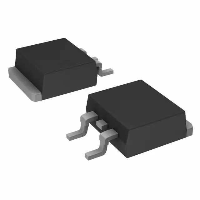
The Vishay VS-25TTS12SLHM3 is a standard-recovery SCR (silicon-controlled rectifier) rated for 1.2 kV off-state voltage and 25 A RMS on-state current, housed in a TO-263AB (D²PAK) surface-mount package. Typical applications include AC motor control, power-supply pre-charge circuits, battery chargers, and industrial welding equipment where a rugged, medium-current thyristor is needed. The D²PAK footprint is large enough for hand-soldering with a decent iron and a bit of practice — the exposed tab carries the cathode connection and doubles as the primary thermal path, so a good solder joint on that tab is what keeps the junction temperature under control at 16 A average current.
For a procurement team, that means this part is still in current manufacture, has a defined supply channel through Vishay's distribution network, and is qualified to the automotive stress tests (preconditioning, temperature cycling, HTRB, H3TRB, etc.) that the AEC-Q101 standard demands. The ROHS3 compliance is also confirmed, so no conflict with EU RoHS directives.
Gate drive and holding current — what to budget
The gate trigger current is specified at 45 mA maximum, with a gate trigger voltage of 2 V maximum. That's a moderate drive requirement — a standard optocoupler or a small-signal transistor can drive it, but the 45 mA figure means you're not driving it directly from a logic pin without a buffer. The holding current is 150 mA maximum, which is on the higher side for a 25 A RMS device; it means the SCR will tend to stay latched once triggered unless the load current drops below that threshold. For inductive loads or pulsed DC applications, check that the minimum load current exceeds 150 mA to avoid premature commutation. The off-state leakage is 10 mA maximum at rated voltage — a figure to consider when sizing bleeder resistors or estimating standby losses in a power supply.
Surge current and on-state voltage — thermal design notes
The non-repetitive surge current rating is 350 A at 50 Hz half-sine wave — a solid number for a 25 A RMS device, giving headroom for motor inrush, capacitor charging, or fault clearing events. The on-state voltage is 1.25 V maximum at rated current, which translates to about 20 W conduction loss at 16 A average — manageable in the D²PAK with proper PCB copper area and thermal vias. The D²PAK tab is the cathode, so the thermal pad on the PCB should connect to the cathode net (typically the load return or negative rail) and have enough copper area to spread the heat. A single-layer board with minimal copper will struggle above 10 A average; a two-layer board with thermal vias under the tab is the practical minimum for continuous 16 A operation.