What the 15 A and 400 V ratings actually mean for your supply
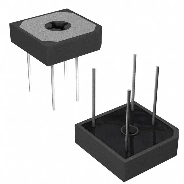
The GBPC1504W-E4/51: The 15 A average rectified current (Io) is the continuous DC output the bridge can deliver into a resistive or capacitive load at 25°C ambient with the case bolted to a heatsink. Derate that figure as the ambient climbs — at 50°C you are realistically looking at 12 A continuous unless you have forced air over the fins. The 400 V peak reverse voltage (Vrrm) gives you comfortable margin on a 240 VAC line (340 V peak) and even covers the 277 VAC line (392 V peak) used in some industrial lighting, though I would keep a 1.2× derating factor for surge events. Forward drop is 1.1 V typical at 7.5 A — half the rated current. That means at full 15 A the Vf will be higher (datasheet curve shows about 1.2 V), so conduction loss sits around 18 W. The GBPC-W package with its center mounting hole needs to be bolted to a heatsink with thermal compound; without one the junction cooks quickly above 10 A.
Package and board-fit — the GBPC-W footprint
The 4-Square GBPC-W package is a through-hole part with four solderable tabs plus a 5.2 mm diameter center hole for a #10 screw to a heatsink. The terminal spacing is 10.9 mm between centers on each side, so the PCB layout needs four plated holes on a 10.9 mm square grid plus the center mounting hole. The package stands about 11 mm above the board; the metal base is electrically isolated from the die, so no insulating washer is needed if you use a grounded heatsink. Vishay ships this in bulk — loose pieces in a bag or tube, not tape-and-reel. Expect to hand-place or use a tube feeder; no automated pick-and-place for a through-hole part this size.
Temperature range and where it works
The 150°C limit is only usable if the case temperature stays low enough — with 18 W dissipation and a 10°C/W junction-to-case thermal resistance, the case needs to be under 120°C to keep Tj below 150°C.