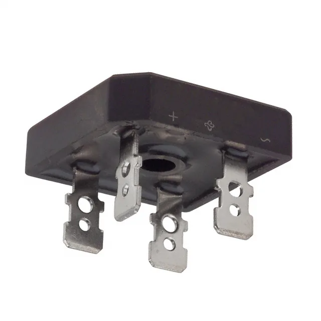
12 A continuous, 200 V peak — the load and line limits
The GBPC1202-E4/51: Rated for 12 A average rectified output current (Io) in a single-phase bridge configuration. For a 12 A supply, the bridge itself is the bottleneck — the heatsinking and airflow around the GBPC package determine whether that rating is achievable in the enclosure. The 200 V peak reverse voltage (Vrrm) sets the maximum AC input peak the bridge blocks. For a 120 VAC line (170 V peak) there is 30 V of headroom; for 240 VAC (340 V peak) this part is not suitable — the 200 V rating would be exceeded on every half-cycle. The 5 µA reverse leakage at that 200 V rating is low enough to ignore in most power budgets, but it doubles with temperature, so a hot-running supply sees higher standby loss than the 25°C datasheet figure suggests.
Forward drop and conduction loss budget
Forward voltage is 1.1 V maximum at 6 A forward current. At the full 12 A rating, the Vf will be higher — expect roughly 1.2–1.3 V based on the silicon die area typical of a GBPC-sized bridge. Two diodes conduct on each half-cycle, so the total conduction loss at 12 A is around 2 × 1.2 V × 12 A = 28.8 W, which the GBPC package must dissipate through the QC terminals and any attached heatsink.
GBPC package and QC terminal mounting
Housed in the 4-Square GBPC package with QC (quick-connect) terminals. The four tab terminals accept 0.250-inch female quick-disconnect crimp terminals — no soldering required for the power connections, which speeds assembly and field replacement. The GBPC case itself is not hermetic, so conformal coating is recommended if the assembly sees condensation or washdown.